Wheel assembly and wheelchair

a wheel assembly and wheelchair technology, applied in the field of wheelchairs, can solve the problems of time-consuming and unproductive constant backing and pivoting, the inability of the wheel chair to achieve side-to-side lateral motion, and the significant difficulty of maneuvering in tight quarters such as bathrooms and elevators, so as to achieve the maximum circularity of the wheel assembly circumference

Active Publication Date: 2007-09-04
LAMPRICH MEDICAL
View PDF22 Cites 11 Cited by
  • Summary
  • Abstract
  • Description
  • Claims
  • Application Information

AI Technical Summary

Benefits of technology

[0010]A wheelchair of this invention comprises a pair of main wheels attached to hubs that rotate on axles by a plurality of spokes. Small outer rotatable wheels and wheel bearings are positioned on the main wheels between the spokes. The small outer rotatable wheels are positioned perpendicularly to the main wheels as close together as possible. The outer tire surfaces of the small rotatable wheels define an essentially continuous wheel assembly circumference. Preferably, the outer tire surfaces are shaped to maximize the circularity of the wheel assembly circumference. An optional brake assembly is attached to the wheelchair for preventing the outer small rotatable wheels from rotating when the wheelchair is moved forward or backward.
[0011]The wheelchair of this invention comprises a frame, one or more axles, a pair of rearward main wheel assemblies as defined above attached to the one or more axles and a pair of front castor wheels. The wheelchair is hand-propelled using hand rails mounted on the main wheels and as mentioned above, it can optionally include a brake assembly for preventing rotation of the small outer rotatable wheels.

Problems solved by technology

However, the wheelchair cannot achieve side-to-side lateral motion.
This may be tolerable in some situations; however, the inability to move laterally causes significant difficulty in maneuvering in tight quarters such as bathrooms and elevators.
Even in a confined office or work setting, the constant backing and pivoting is time consuming and unproductive.
However, this type of chair requires the constant presence of an assistant since it cannot be hand propelled.

Method used


Image

  • Wheel assembly and wheelchair
  • Wheel assembly and wheelchair
  • Wheel assembly and wheelchair

Examples


Embodiment Construction

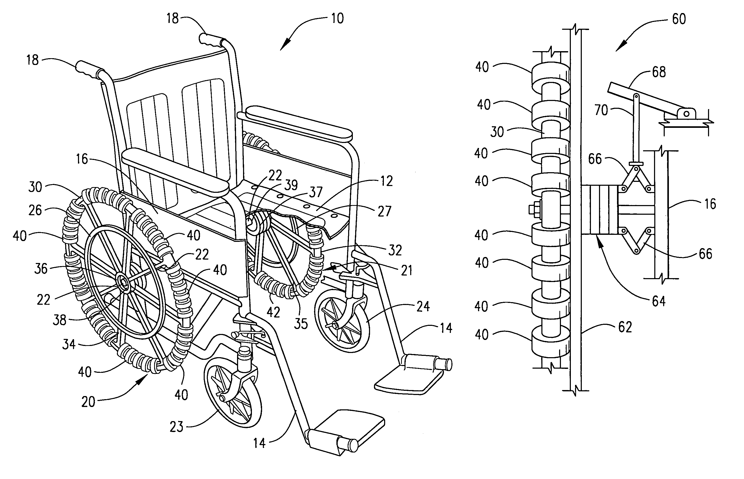
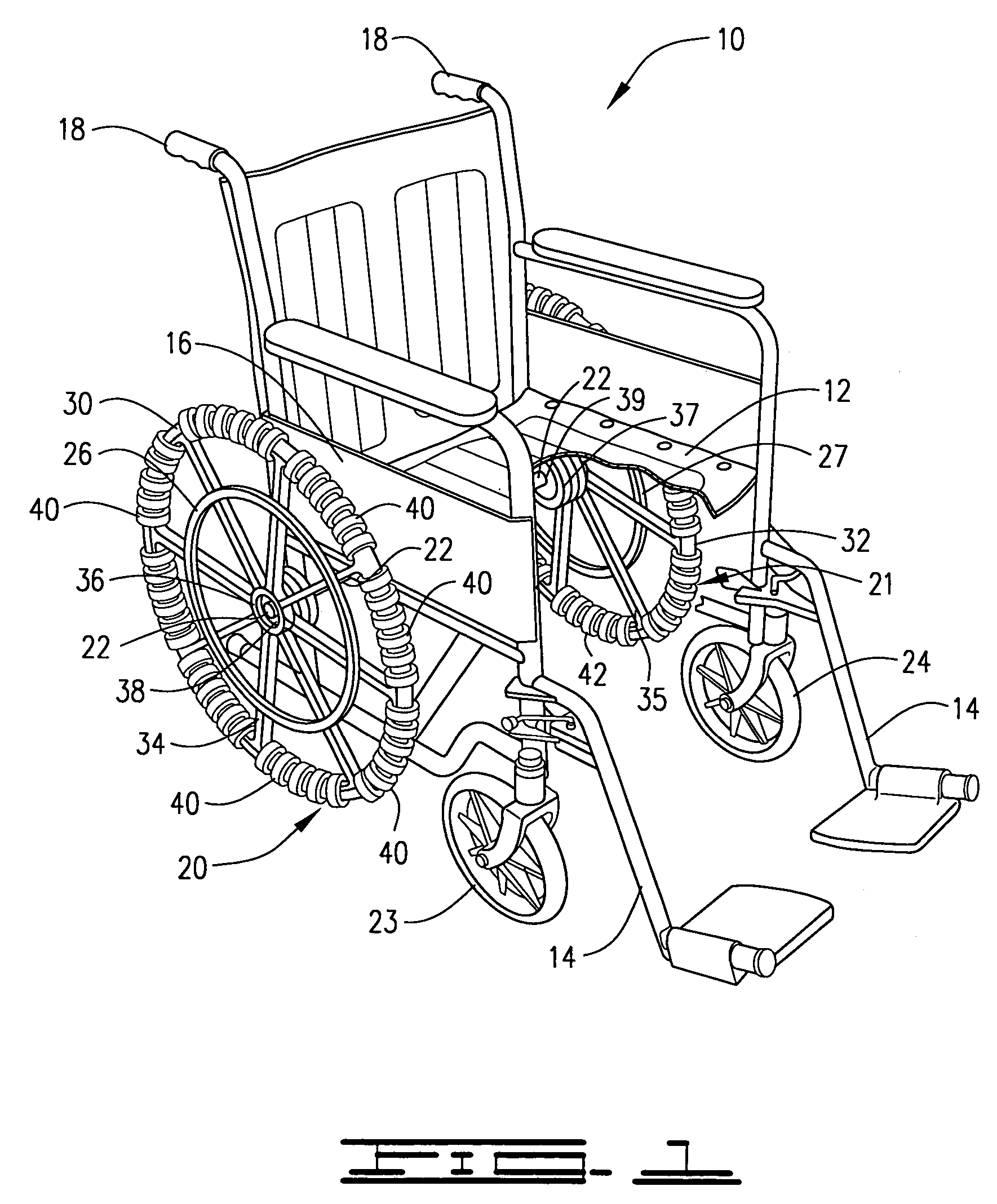
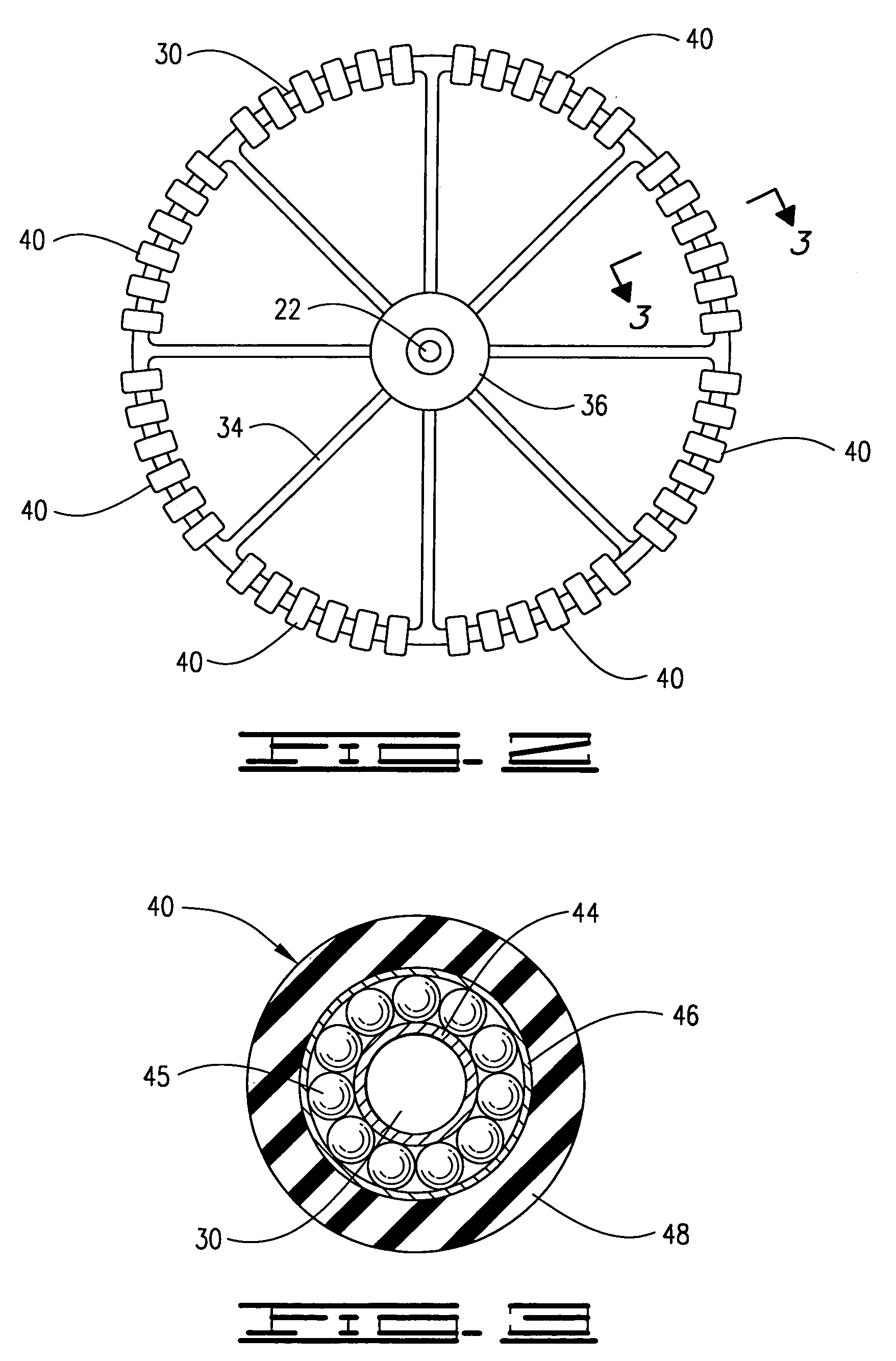
[0020]As mentioned, a wheel assembly of this invention is capable of forward-reverse movement as well as lateral movement. Referring to FIG. 1, a main wheel assembly 20 of this invention is shown attached to a wheelchair 10. The main wheel assembly 20 includes a main wheel 30, radially extending spokes 34 and a central hub 36 that includes a bearing 38. A plurality of small rotatable outer wheels 40 are positioned laterally on the main wheel as will be described further hereinbelow.

[0021]Referring still to FIG. 1, the wheelchair 10 of this invention is illustrated comprising a frame 16 having a seat assembly 12 and a footrest assembly 14 mounted thereon, and having main wheel assemblies 20 and 21 and castor wheels23 and 24 attached thereto. The seat, footrest and frame assemblies may be connected by welding, bolting or other means. Extended push handles 18 are attached to the frame to enable an attendant to push and direct the wheelchair.

[0022]A rolling movement is achieved by the m...


PUM


Abstract

A wheel assembly having multiple small rotatable wheels mounted laterally thereon whereby lateral movement as well as forward and backward movement is provided. A pair of the wheel assemblies are utilized on a hand-propelled wheelchair that can be moved laterally as well as in the standard forward-reverse motion. The wheelchair comprises a frame, one or more axles, a pair of main wheels rotatable on the one or more axles, and a plurality of small rotatable outer wheels positioned laterally on the main wheels.

Description

BACKGROUND OF THE INVENTION[0001]1. Field of the Invention[0002]This invention relates to an improved wheel assembly and wheelchair, and in particular to a wheel assembly having multiple small rotatable wheels mounted laterally on a main wheel whereby lateral movement as well as forward and backward movement is possible.[0003]2. Description of the Prior Art[0004]Wheelchairs are available in a variety of shapes and sizes. The traditional wheelchair design, whether powered, manual or pushed by another person, has two main, large diameter, side mounted wheels having fixed parallel positions and having hand rails attached thereto. Because of the fixed parallel positions of the main wheels, movement is generally restricted to pivoting, straight line or curved movement. Curved and pivoting movement is attained by rotating the main wheels at different speeds or in opposite directions. However, the wheelchair cannot achieve side-to-side lateral motion.[0005]In order to shift position latera...

Claims


Application Information

Patent Timeline
Patent Type & Authority Patents(United States)
IPC IPC(8): B60B5/04B62M1/14
CPCA61G5/02A61G5/10A61G5/1018B60B19/003A61G5/1008A61G5/1024A61G5/1035B60B2310/302B60B2380/12B60Y2200/84
Inventor LAMPRICH, LONNIE JAYLAMPRICH, BRADLEY KEITH
Owner LAMPRICH MEDICAL
Why Eureka
Try Eureka