Liquid container and printing apparatus using the same

a technology of printing apparatus and liquid container, which is applied in the field of liquid container and printing apparatus using the same, can solve the problems of difficult to return pigment colorant settling of ink, insufficient to substantially eliminate the settling of pigment colorant of ink, and achieve the effect of facilitating agitation and mixing of ink portions having different concentrations and enhancing the uniformity of ink concentration

Inactive Publication Date: 2007-09-04
CANON KK
View PDF23 Cites 10 Cited by
  • Summary
  • Abstract
  • Description
  • Claims
  • Application Information

AI Technical Summary

Benefits of technology

[0017]Suppose that the purging operation for starting the printer or a very small amount of printing is carried out in a state wherein the pigment colorant settles in the liquid storage chamber during long quiescent operation of the printer as shown in FIG. 10B. When the ink in the area 15c having a high pigment concentration moves into the negative pressure generating member 11 via the communicating portion 9 without the application of sufficient stirring force respect to ink in the liquid storage chamber. It is not enough to substantially eliminate the settling of pigment colorant of the ink if the liquid container 1 is simply stirred on the carriage.
[0020]The present invention has been made to eliminate the above-mentioned problem, and an object thereof is to provide a liquid container using a the gas-liquid exchange operation, having the liquid storage chamber for directly accommodating ink and the chamber for accommodating the negative pressure generating member retaining ink simple in structure with a high storage efficiency by taking account of a settling characteristic inherent to dispersed pigment.
[0021]In other words, a reliable liquid container simple in structure with a high storage efficiency is provided, which is capable of supplying ink outside at a stable negative pressure and free from the inconvenience even if it is used after the long term non-used state while storing the pigment ink. Also, a printer using this liquid container is provided. In this regard, while the settling phenomenon of the pigment dispersion is taken up as a problem in the above description and without limitation, further it is object of the present invention to provide means for obtaining an equal effect with respect to any of various materials dispersed in the printing liquid used for the ink-jet printer.
[0029]According to the present invention, when the liquid is supplied to the chamber for accommodating the negative pressure generating member from the liquid storage chamber, the liquid passing through the second communication opening is supplied to the negative pressure generating member in response to the gas-liquid exchange operation via the first communication opening with the concentration distribution of the liquid relieving. The liquid having a concentration suitable for printing is supplied to a printing head from a supply port to be able to print optimally.
[0031]Also, since the agitation and mixing of the ink portions having different concentrations are facilitated, which ink portions flow into the intermediate chamber through the plurality of holes by air introduced due to the gas-liquid exchange, it is possible to further enhance the uniformity of the ink concentration.

Problems solved by technology

However, it was found that the liquid container provided with the above-mentioned liquid storage chamber for directly accommodating ink and the chamber for accommodating the negative pressure generating member retaining ink has a significant problem.
It is not enough to substantially eliminate the settling of pigment colorant of the ink if the liquid container 1 is simply stirred on the carriage.
In addition, if a long term non-used state continues again thereafter, further the pigment colorant settling occurs due to supply ink to the printing head via the negative pressure generating member which the pigment colorant settling of the ink is difficult to return.
When the ink having a high pigment concentration is supplied from the negative pressure generating member to the printing head to carry out the printing operation, there is a problem that not only the print quality is largely damaged but also the ink is not normally ejected from the printing head for the reason that dispersed pigment particles begin to coagulate with each other, resulting in the clogging of a nozzle in the printing head.

Method used


Image

  • Liquid container and printing apparatus using the same
  • Liquid container and printing apparatus using the same
  • Liquid container and printing apparatus using the same

Examples


first embodiment

[0046](Total Structure)

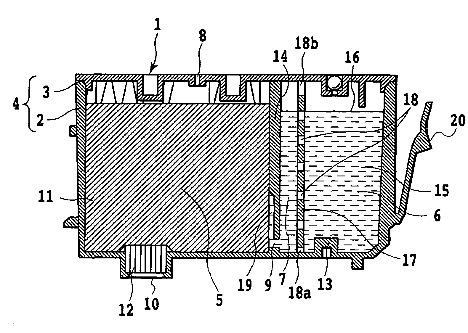
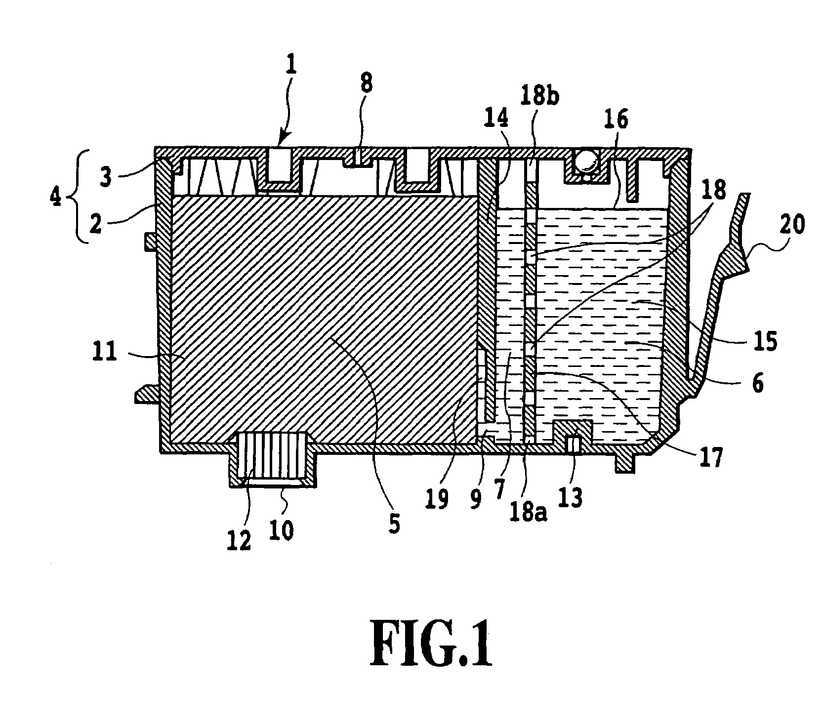
[0047]FIG. 1 is a schematic sectional view illustrating a liquid container according to an embodiment of the present invention. The liquid container 1 includes a housing 4 consisting of a tub 2 and a cover 3 made of synthetic resin and the interior thereof is divided into two spaces by a partition wall 14 having a communicating portion 9. One of the spaces defines a liquid storage chamber 6 closed except for the communicating portion 9 in the partition wall 14, for directly storing an ink 15. Other of the spaces defines a chamber 5 for accommodating a negative pressure generating member 11 impregnated with liquid. The ink 15 is a pigment ink.

[0048]On the upper portion of a wall defining the chamber 5 for accommodating the negative pressure generating member, there is an atmospheric communicating port 8 for introducing outside air into the liquid container 1 as the ink is consumed. On a wall surface of a lower wall opposite to the wall in which the atmospheric ...

second embodiment

[0068]A second embodiment of the present invention will be described with reference to FIG. 6.

[0069]Different from the structure shown in FIG. 1 wherein the partition wall 17 having the plurality of communication holes 18 is provided, the chamber 5 for accommodating the negative pressure generating member is communicated with the liquid storage chamber 5 through a duct 27 extending upward from the vicinity of the bottom of the liquid storage chamber 6 while coupled to the communicating portion 9. That is, the intermediate chamber 7 in FIG. 1 corresponds to the interior space in the duct 27, and the communication holes 18 provided in the partition wall 17 correspond to a plurality of through-holes provided on the lateral wall of the duct.

[0070]FIG. 7 illustrates a modification of the second embodiment wherein the present invention is applied to a prior art liquid container different from that shown in FIG. 10. FIG. 7A is a schematic view of the inventive liquid container before a duc...

third embodiment

[0074]Subsequently, a third embodiment will be described below. A structure shown in FIG. 9 is different in the construction of the communicating portion 9 from that of FIG. 6; i.e., the communicating portion 9 is divided into an upper region 9a and a lower region 9b. The upper region 9a of the communicating portion 9 directly communicates with the liquid storage chamber 6 to be a route for sending outside air from the chamber 5 for accommodating the negative pressure generating member into the liquid storage chamber 6. On the other hand, the lower region 9b of the communicating portion 9 communicates with the duct 27 and with the liquid storage chamber 6 via the through-holes 18 in the tubular wall thereof. Of course, in this structure, it goes without saying that the first effect of the present invention is obtainable. In this embodiment (see FIG. 9), different from the second embodiment (see FIG. 6), air obtained by the gas-liquid exchange is not taken into an interior space with...


PUM


Abstract

An intermediate chamber 7 is provided in a liquid storage chamber 6 of a liquid container 1, for separating the liquid storage chamber 6 from a chamber 5 for accommodating a negative pressure generating member. The intermediate chamber 7 communicates with both of the liquid storage chamber 6 and the chamber 5 for accommodating the negative pressure generating member, and further communicates with the liquid storage chamber 6 via a plurality of small openings 18 provided upward from the bottom thereof.

Description

FIELD OF THE INVENTION[0001]The present invention relates to a liquid container mounted to an ink-jet printing apparatus and a printing apparatus using the same.DESCRIPTION OF THE RELATED ART[0002]Generally, an ink cartridge used as a liquid container in a field of the ink-jet printing is provided with a structure for adjusting an inner pressure of ink of the ink cartridge for performing well the ink supply to a printing head for ejecting ink. The negative pressure of the ink cartridge can be generated for retaining a meniscus formed in an ink-ejecting section of the printing head by providing a negative generating member in the ink cartridge.[0003]Recently, the ink-jet printing technology has been significantly developed, and thus photorealistic print have easily been obtainable. However, in comparison with a silver-salt photography, since the durability of the print (such as light resistance or gas-resistance) is inferior to that in the silver-salt photography, there has been the ...

Claims


Application Information

Patent Timeline
Patent Type & Authority Patents(United States)
IPC IPC(8): B41J2/175
CPCB41J2/17513B41J2/17523B41J2/17556B41J2/17503
Inventor YAMAMOTO, HAJIMEHATASA, NOBUYUKI
Owner CANON KK
Why Eureka
Try Eureka