Fuel pump

a fuel pump and pump body technology, applied in the direction of positive displacement liquid engine, piston pump, liquid fuel engine, etc., can solve the problems of easy vaporization of fuel that has been drawn into the casing, decreased pressurizing force of the fuel pump, and insufficient quantity of fuel discharged from the pump

Inactive Publication Date: 2007-09-04
AISAN IND CO LTD
View PDF12 Cites 3 Cited by
  • Summary
  • Abstract
  • Description
  • Claims
  • Application Information

AI Technical Summary

Benefits of technology

[0007]In a fuel pump utilizing an impeller in which bottom portions of a pair of concavities formed in upper and lower faces of the impeller communicate, it is preferred that the fuel flows smoothly through a through-hole that communicates the pair of upper and lower concavities. When it is difficult for the fuel to pass through the through-hole, some of the fuel that has been drawn into the casing easily vaporizes. When vapor is formed, the pressurizing force by the fuel pump is decreased and the quantity of the fuel discharged from the pump is likely to be insufficient. Since fuel tends to vaporize at high temperatures, serious problems occur if the fuel does not pass smoothly through the through-holes, especially when the fuel is at high temperatures.
[0008]The present invention teaches a fuel pump in which fuel can smoothly pass through a through-hole that communicates a pair of upper and lower concavities. The present invention effectively improves the pump performance. Especially, the fuel pump of the present invention prevents the pump performance from decreasing that often occurs at high fuel temperatures.
[0009]After carefully examining the conventional impeller shown in FIGS. 9 to 11, the inventors have discovered that the prior art through-hole communicating the pair of upper and lower concavities is not suitably designed for promoting smooth fuel flow. The inventors have found that pump performance can be increased by improving the design of the through-holes. In particular, vaporization of fuel at high temperatures is effectively reduced due to the improvement of the through-holes, and pump performance at high fuel temperatures may be improved.

Problems solved by technology

When it is difficult for the fuel to pass through the through-hole, some of the fuel that has been drawn into the casing easily vaporizes.
When vapor is formed, the pressurizing force by the fuel pump is decreased and the quantity of the fuel discharged from the pump is likely to be insufficient.
Since fuel tends to vaporize at high temperatures, serious problems occur if the fuel does not pass smoothly through the through-holes, especially when the fuel is at high temperatures.
After carefully examining the conventional impeller shown in FIGS. 9 to 11, the inventors have discovered that the prior art through-hole communicating the pair of upper and lower concavities is not suitably designed for promoting smooth fuel flow.

Method used


Image

  • Fuel pump
  • Fuel pump
  • Fuel pump

Examples


first embodiment

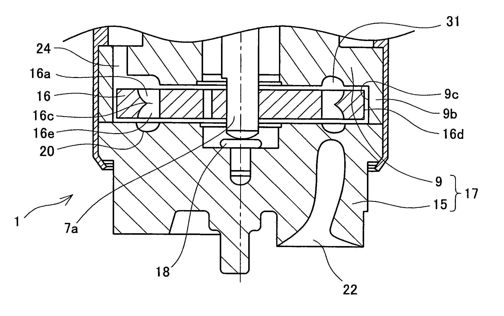
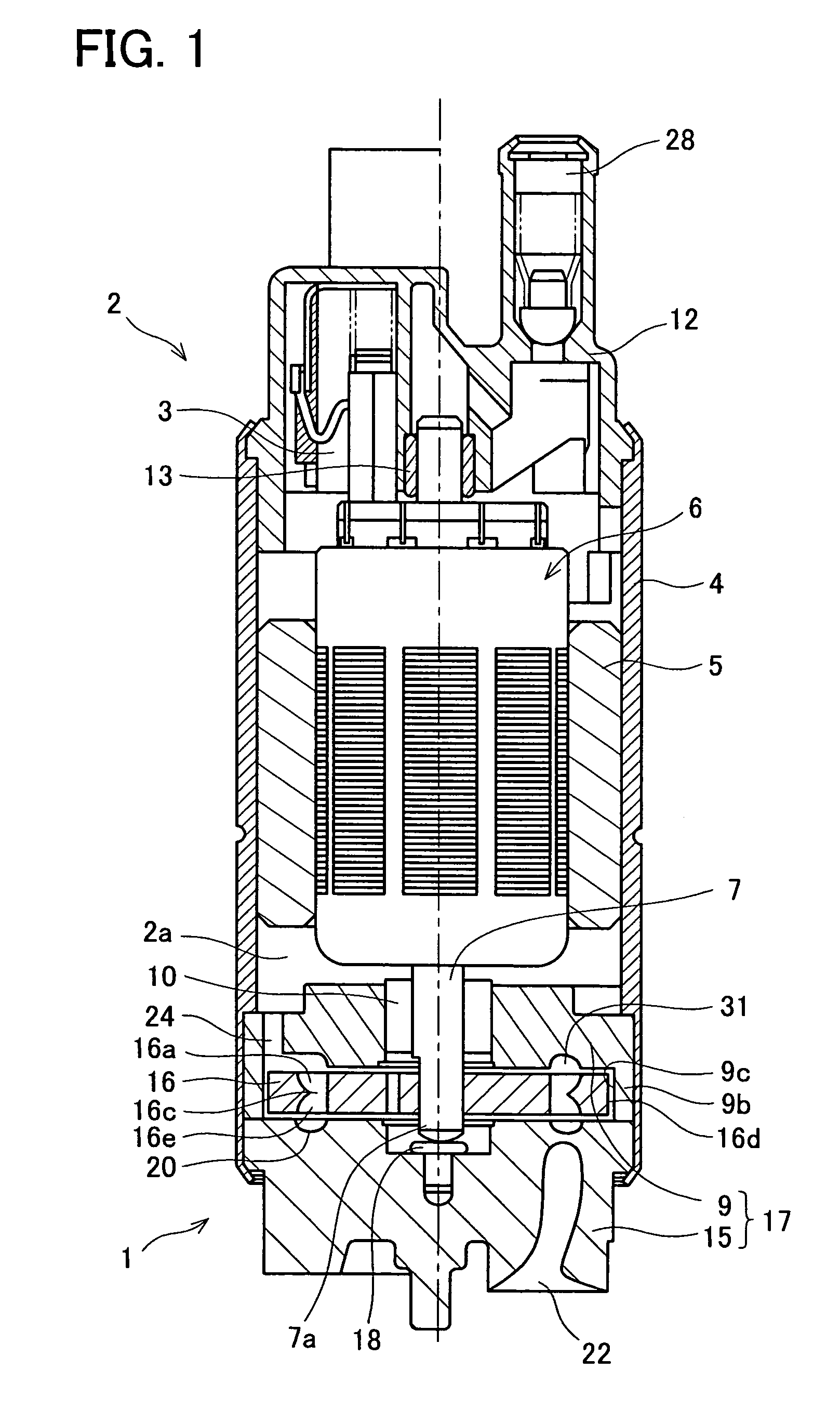
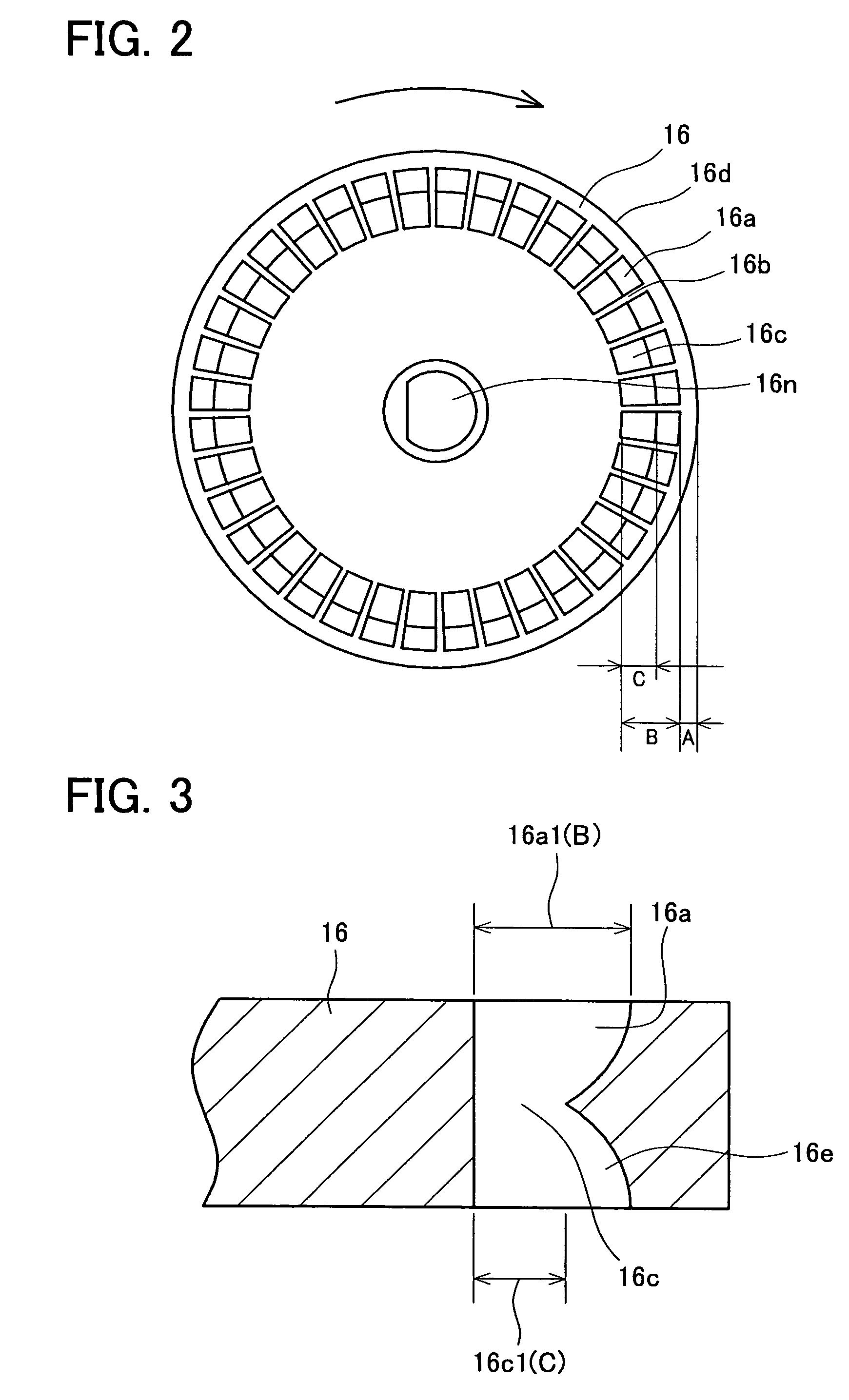
[0044]the present invention is described referring to FIGS. 1 to 5. FIG. 1 shows a cross-sectional view of the fuel pump of the present embodiment, FIG. 2 shows a plane view of an upper face of an impeller of this fuel pump, FIG. 3 shows a cross-sectional view showing peripheral portion of the impeller, and FIG. 4 shows a cross-sectional view showing essential part of the fuel pump. Further, components that are identical in the conventional fuel pump and in the present embodiment have the same reference numbers assigned thereto.

[0045]The fuel pump of the present embodiment is used in a motor vehicle, the fuel pump being utilized within a fuel tank and being utilized for supplying fuel to the engine of the motor vehicle. As shown in FIG. 1, the fuel pump is composed of a pump section 1 and a motor section 2 for driving the pump section 1. The motor section 2 is provided with a brush 3, a magnet 5 located within an approximately cylindrical housing 4, and a rotating member 6 concentri...

second embodiment

[0064]FIG. 6 shows an enlarged cross sectional view of the impeller in the A group of concavities 66a is formed in an upper face of the impeller 66, and a group of concavities 66e is formed in an lower face of the impeller 66 as shown in FIG. 6. Bottom portions of the pair of upper concavities 66a and lower concavities 66e communicate via through-holes 66c. Each of the through-holes 66c is formed within a region at the inner side of each of concavities 66a, 66e. The bottom portions of the upper and lower concavities 66a, 66e are separated by a partitioning member 66h. The partitioning member 66h is formed from a wall 66g1 at the outer side of the upper concavity 66a and a wall 66g2 at the outer side of the lower concavity 16e, and is formed at a central portion of the impeller 66 relative to the direction of thickness thereof. The wall faces 66g1 and 66g2 located at the outer side of the concavities 66a, 66e are curved, and extend towards the bottom portions to make contact with a ...

third embodiment

[0068]FIG. 7 shows an enlarged cross sectional view of an impeller of the A groups of concavities 76a is formed in an upper face of an impeller 76 and a groups of concavities 76e is formed in an lower as shown in FIG. 7. Bottom portions of the pair of upper and lower concavities 76a, 76e communicate via a through-hole 76c. Each of the through-holes 76c is formed at the inner side of each of the concavities 76a, 76e. The bottom portions of the upper and lower concavities 76a, 76e are partitioned by a partitioning member 76h.

[0069]Inclined faces 76j are formed at the inner sides of the upper and lower concavities 76a, 76e formed in the impeller 76. These inclined faces 76j are inclined outwardly in the radial direction towards the bottom. The impeller 76 of the fuel pump of the present embodiment differs in this point from the impeller 66 of the fuel pump of the second embodiment.

[0070]The impeller 76 is formed by a resin which is molded within a molding die and extracted from the d...


PUM


Abstract

A fuel pump in which fuel can pass smoothly through through-holes of an impeller is taught. Through-holes communicate concavities formed in upper and lower faces of the impeller. These through-holes are formed at an inner side region within the concavities. When the impeller rotates, the rotational speed of the portion provided with the through-holes is slower than in the case where these through-holes are formed at the outer side region within the concavities. As a result, the fuel in the vicinity of the through-holes within the concavity has a slower rotational speed, and consequently the fuel passes easily through the through-holes.

Description

CROSS-REFERENCE[0001]The present application claims priority based on Japanese Patent Application 2003-162785 filed on Jun. 6, 2003. The specification and figures of that Japanese application are hereby incorporated by reference within the specification and figures of the present application.FIELD OF THE INVENTION[0002]The present invention relates to a fuel pump for drawing in a fuel such as gasoline etc., increasing the pressure thereof, and discharging the pressurized fuel.BACKGROUND OF THE INVENTION[0003]As disclosed in PCT International Publication WO99-07990, a fuel pump is provided with a substantially disc-shaped impeller that rotates within a casing. As shown in FIG. 9, a group of concavities 36a is formed in an upper face of the impeller 36, and the group of concavities 36a is formed along the circumference direction of the impeller 36 in an area located inwardly from an outer circumference 36d of the impeller 36 by a distance shown by “A” in FIG. 9. Each of concavities 36...

Claims


Application Information

Patent Timeline
Patent Type & Authority Patents(United States)
IPC IPC(8): F01D1/12F02M37/10F02M37/08F04D5/00F04D7/02F04D29/22F04D29/24H01L27/10
CPCF02M37/08F04D29/188
Inventor IKEYA, MASAKI
Owner AISAN IND CO LTD
Why Eureka
Try Eureka