
Convection oven with turbo flow air nozzle to increase air flow and method of using same

a technology of air nozzle and convection oven, which is applied in the field of ovens, can solve the problems of inefficient operation, increased cost and cost of fan size and ductwork, and increased difficulty in maintaining the temperature of the optimal workpiece, so as to improve the degree of air flow and improve the efficiency of operation.

Inactive Publication Date: 2007-09-04
INT THERMAL SYST
View PDF23 Cites 21 Cited by
  • Summary
  • Abstract
  • Description
  • Claims
  • Application Information

AI Technical Summary

Benefits of technology

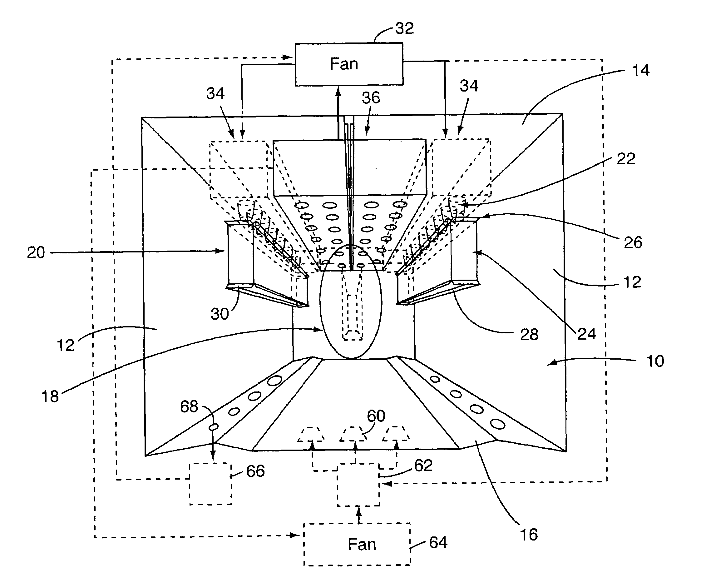
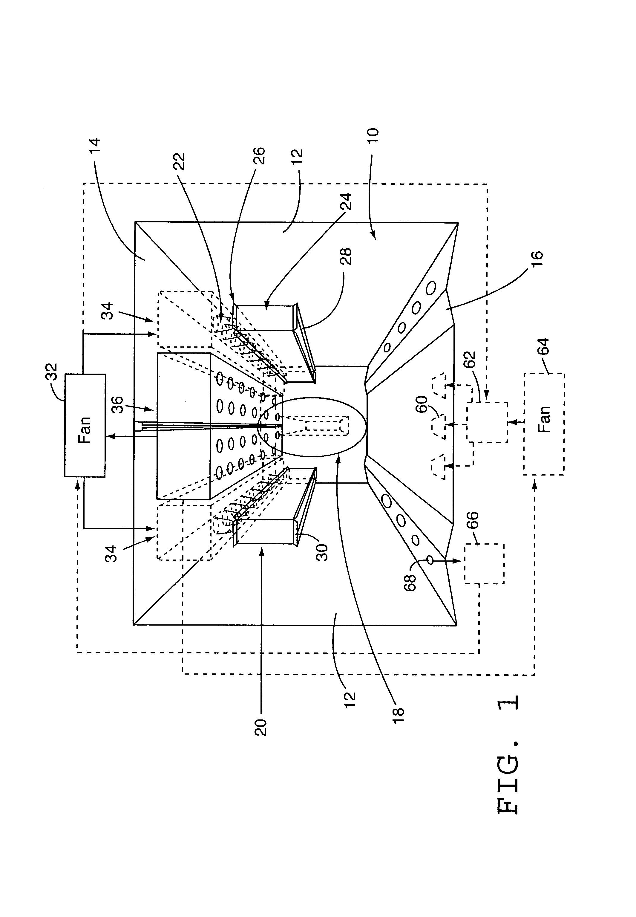
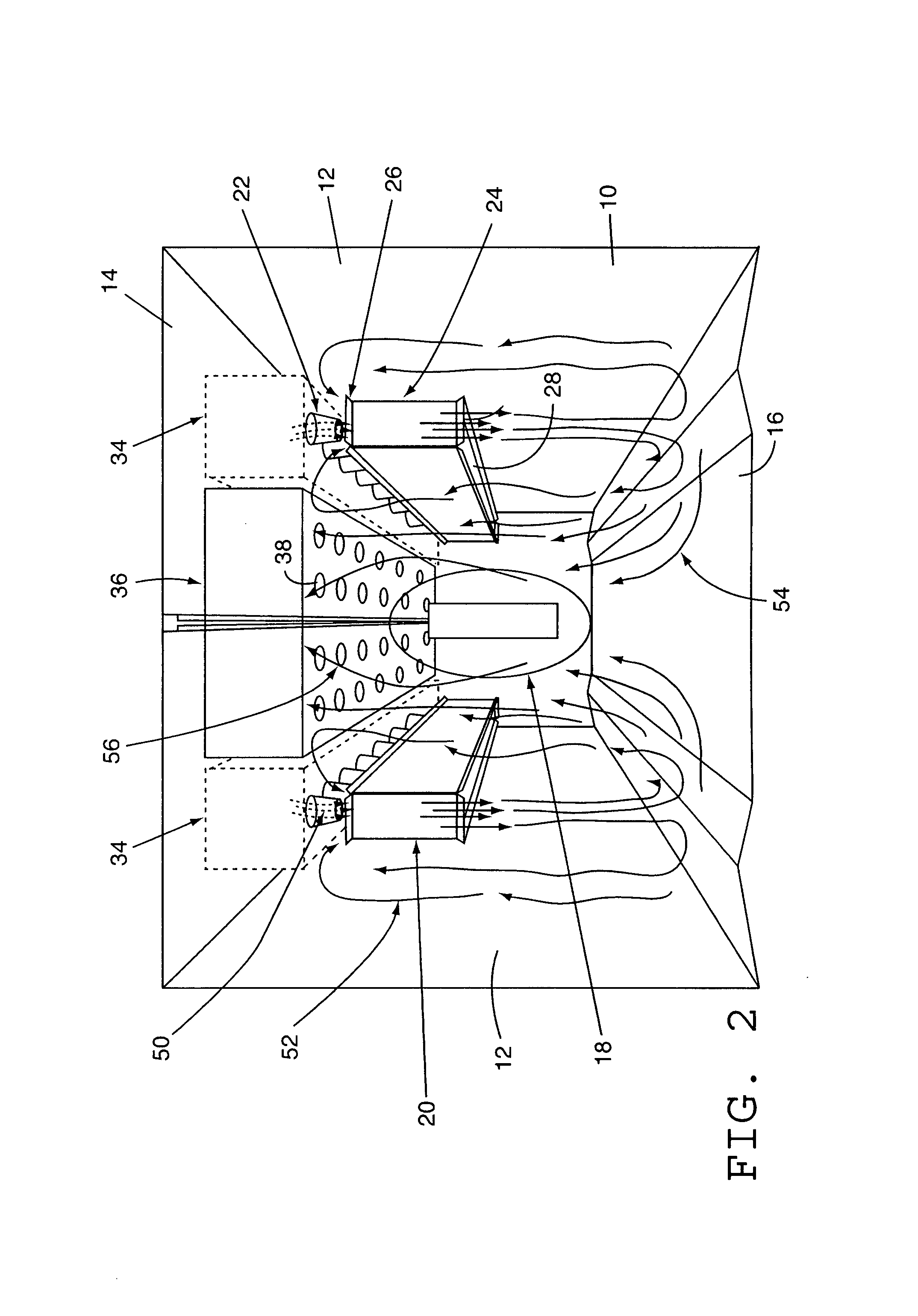
[0006]The present invention provides a convection oven, and method of using same, that achieves a substantially enhanced degree of air flow through the use of a turbo flow nozzle design. Ovens contemplated by the present invention may be used to dry powder coated paint on metal articles or for any other application. A convection oven in accordance with the present invention employs turbo flow air nozzles along with appropriate ductwork to create a specific air flow pattern to provide a high velocity airflow in a heat transfer zone with a smaller fan size and ductwork, and thus may be operated more efficiently than conventional industrial convection ovens.
[0008]During operation of a convection oven in accordance with the present invention convection airflow through a heat transfer zone is enhanced by the use of the turbo flow air nozzles. Airflow from a recirculation fan flows through a supply duct to the one or more supply nozzles to produce a high velocity air flow that flows through the air entrainment and mixing section, turns and flows through the heat transfer zone, and flows through a return path, e.g., via a return duct, back to the recirculation fan. Air from the interior of the oven is entrained by the high velocity air directed into the air entrainment and mixing section from the supply nozzles and flows through the air entrainment and mixing section, is directed through the main heat transfer zone, and then turns and flows back into the air entrainment and mixing section.

Problems solved by technology

If the work piece temperature is allowed to climb too high the work piece will be damaged.
Maintaining optimum work piece temperatures is made more complicated for certain work pieces, such as metal articles, which act as heat sinks affecting the oven temperature, often significantly.
However, the fan size and ductwork needed to provide the required air velocity throughout an oven is often expensive and inefficient.
However, the use of high velocity air nozzles alone is limited in that it does not provide control of the quantity and direction of air flow through the oven.

Method used


Image

  • Convection oven with turbo flow air nozzle to increase air flow and method of using same
  • Convection oven with turbo flow air nozzle to increase air flow and method of using same
  • Convection oven with turbo flow air nozzle to increase air flow and method of using same

Examples


Embodiment Construction

[0015]An exemplary convection oven 10 in accordance with the present invention, incorporating turbo flow air nozzles to increase air flow therethrough, will be described in detail first with reference to FIG. 1. The present invention may be embodied in any otherwise generally conventional industrial convection oven design as used for the heating of any type of work piece for any desired purpose. For example, the present invention may be implemented in a conventional tunnel type oven, through which work pieces are moved in a continuous work flow, via conveyors supporting the work pieces from either above or below, or in tunnel or entirely enclosed ovens in which work pieces are placed in position for heating. Such ovens may be heated in any conventional manner. The present invention may be incorporated in all or any selected zones of an oven that includes, for example, one or more come-up zones, used to elevate the temperature of a work piece quickly and uniformly to a desired bake t...


PUM


Abstract

A convection oven that achieves a substantially enhanced degree of air flow through the use of a special nozzle design. Turbo flow air nozzles create an air flow pattern to provide higher velocity airflow with a smaller fan size and ductwork. The turbo flow air nozzles include main supply nozzles that direct high velocity air through air entrainment and mixing sections that entrain air from the oven interior to generate the increased air flow in a heat transfer zone of the oven. Appropriate ductwork is provided to direct air from a fan or fans to the supply nozzles to generate a high velocity air flow therethrough.

Description

FIELD OF THE INVENTION[0001]This invention pertains generally to ovens, particularly industrial convection ovens, and more particularly to systems and methods for enhancing air flow within such ovens.BACKGROUND OF THE INVENTION[0002]A variety of different industrial ovens are used for a variety of different purposes. For example, industrial ovens are used to cure powder painted steel sheets and other parts. In this application, and all others, it is necessary to keep the work piece within a desired temperature range for a desired period of time to achieve the desired result. If the work piece temperature is allowed to climb too high the work piece will be damaged. If the work piece temperature is too low or inconstant the work piece may not be cured properly, or at least the time required to cure the work piece, and thus the flow of work product through the oven, is reduced. Maintaining optimum work piece temperatures is made more complicated for certain work pieces, such as metal a...

Claims


Application Information

Patent Timeline
IPC IPC(8): F27B7/14
CPCF27B17/0016F27D7/04
Inventor MITCHELL, JEFFREY C.ZHAO, YOUGUI
Owner INT THERMAL SYST
Learn More