Artificial knee joint

a knee joint and artificial technology, applied in knee joints, prostheses, medical science, etc., can solve the problems of inability to deep flex, inability to move as with biological knee joints, inability to abduct abduction-adduction motion, etc., to achieve smooth flexion-extension operation, easy to acquire balance, and smooth flexion-extension operation

Inactive Publication Date: 2007-09-04
NAKASHIMA PROPELLER +1
View PDF16 Cites 100 Cited by
  • Summary
  • Abstract
  • Description
  • Claims
  • Application Information

AI Technical Summary

Benefits of technology

[0016]In the artificial knee joint of the present invention, the medial condyle of the femoral component, which corresponds to the length between the cut line (BC) that is parallel to a flexion-extension center axis (SEA) and the lower end of the medial condyle of the femur component, is made thicker than the lateral condyle, and the lateral articular surface of the tibial component is made thinner or deeper than the medial articular surface. Accordingly, the joint line, which is a straight line, inclines inwardly, and it is easy to acquire a balance between tension and relaxation of ligaments, particularly the medial collateral ligaments, and smooth flexion-extension becomes possible. In addition, adduction-abduction motion is induced and deep flexion also becomes possible as a result of the inward inclination of the straight joint line. Thus, movement approximating that of a biological knee joint is possible. In this case, inclination of the joint line should be the same as a biological knee joint, which is 1 to 10°, preferably 2 to 5°.
[0017]Furthermore, in the artificial knee joint of the present invention, the line of maximum thickness that longitudinally links the points of maximum thickness in the medial-lateral direction of the medial condyle is set so as to turn outward toward the front. As a result, in co

Problems solved by technology

If ligament balance is compromised, flexion-extension motion will be impaired; and if inward inclination cannot be maintained, adduction-abduction motion whereby the ankles turn out (abduction) during extension and turn inward (adduction) during flexion will not occur, and the same movement as with biological knee joints will not be possible.
However, since the joint line JL is horizontal, there is a disadvantage in that abduction-adduction motion is not induced during flexion-extension and deep flexion is not possible.
However, because the medial and lateral supporting surfaces of the tibial comp

Method used


Image

  • Artificial knee joint
  • Artificial knee joint
  • Artificial knee joint

Examples


Embodiment Construction

[0028]Embodiments of the present invention will be described below with reference to the accompanying drawings.

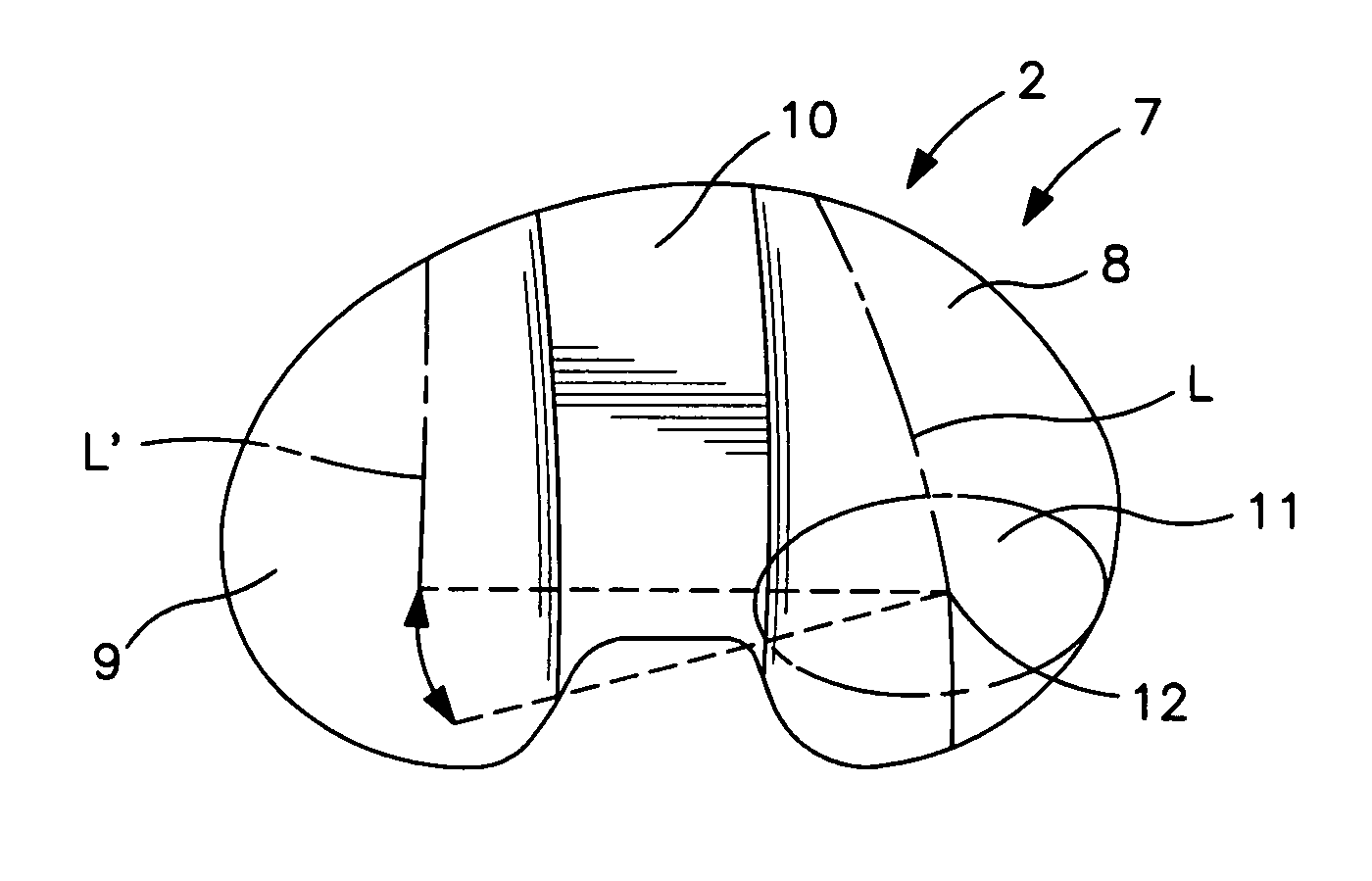
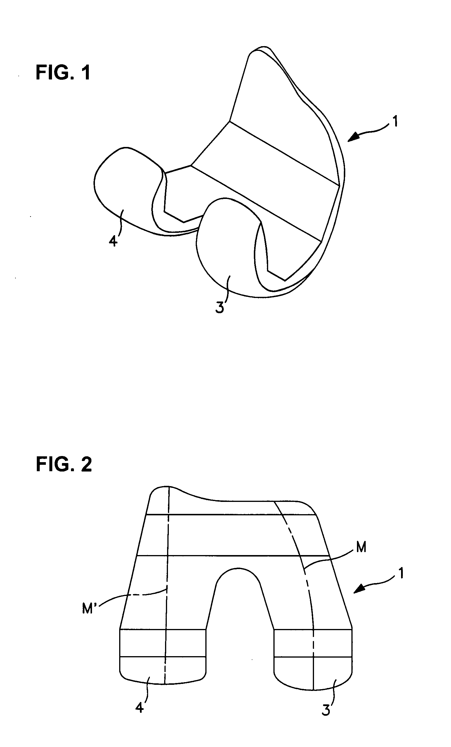
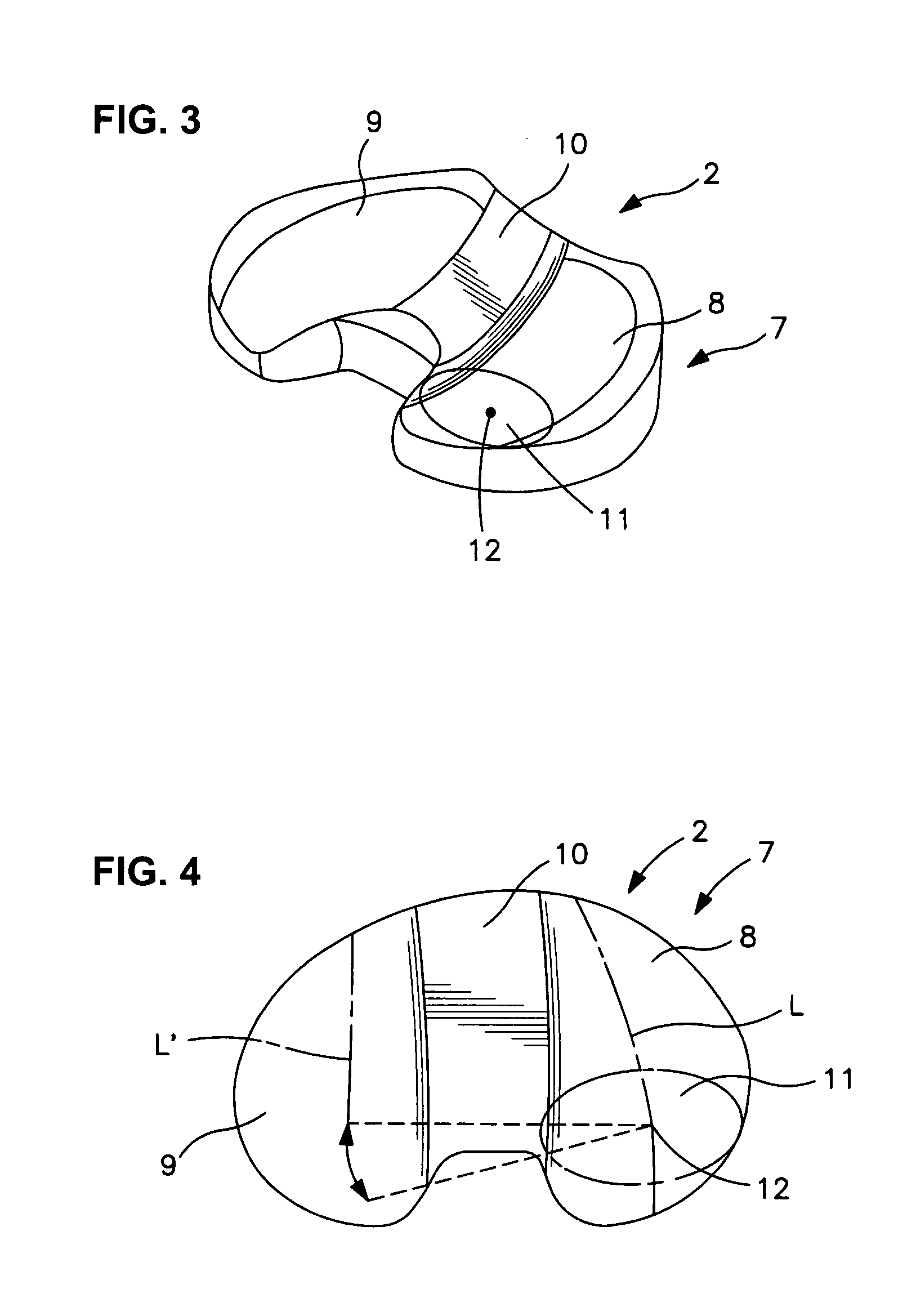
[0029]The artificial knee joint comprises a combination of a femoral component 1 and a tibial component 2. Of these, the femoral component 1 is made from a biocompatible metal, such as titanium alloy, etc. An inlet shape is cut out from the center of the posterior part so that from the side view a medial condyle 3 and a lateral condyle 4 form a substantially round shape, that is, a substantially C shape with the medial condyle 3 thicker than the lateral condyle 4 over an entire region of an angle of flexion-extension as shown in FIG. 5. The femoral component 1 is attached to the distal end of femur 5. There is also a type that is called the PS (posterior stabilized) type where part of the cut-away part is covered by a box to restrict specific movement of the other member, but this is functionally the same. In this case, when the medial condyle 3 and lateral condyle 4 are vi...


PUM


Abstract

An artificial knee joint including a femoral component to be attached to a femur and a tibial component to be attached to a tibia, wherein in the femur component a medial condyle thereof is thicker than a lateral condyle thereof; in the tibial component, a medial articular surface thereof, which supports the medial condyle of the femur component, is thinner or deeper than a lateral articular surface thereof, which supports the lateral condyle of the femur component; and a joint line joining the lowest points of contact surfaces between the medial and lateral condyles of the femur component and the medial and lateral articular surfaces of the tibial component in a longitudinal cross section in a medial-lateral direction is inclined inward at virtually the same angle over the entire region of an angle of flexion-extension.

Description

BACKGROUND OF THE INVENTION[0001]1. Field of the Invention[0002]The present invention relates to an artificial knee joint that will replace the knee joint.[0003]2. Prior Art[0004]The knee joint is replaced with an artificial knee joint when osteoarthritis, rheumatoid arthritis, or bone tumor is contracted or it is traumatized, etc. This artificial knee joint is a combination of a femoral component having two, a medial and a lateral, condyles; and a tibial component having two, a media and a lateral, articular surfaces, which support the respective two condyles. The condyles and articular surfaces must perform the same movements as with biological knee joints.[0005]More specifically, when an artificial knee joint is attached, the balance between tension and relaxation of the ligaments that are present along the space between the femur and the tibia, particularly the collateral ligaments, needs not to be compromised; and the line that joins the lowest points on the contact surfaces be...

Claims


Application Information

Patent Timeline
IPC IPC(8): A61F2/38A61F2/30
CPCA61F2/38
Inventor SUGURO, TORUKURAMOTO, KOICHIYAMAMOTO, KEITARO
Owner NAKASHIMA PROPELLER
Why Eureka
Try Eureka