Multiphase superconducting cable connection structure and multiphase superconducting cable line

a superconducting cable and connection structure technology, applied in the direction of superconducting magnets/coils, magnetic bodies, connection contact material materials, etc., can solve the problems of frp member hardly preventing the movement of the portion, disadvantageous movement of the portion from the installation location,

Inactive Publication Date: 2007-09-04
SUMITOMO ELECTRIC IND LTD
View PDF5 Cites 12 Cited by
  • Summary
  • Abstract
  • Description
  • Claims
  • Application Information

AI Technical Summary

Benefits of technology

[0013]The present invention allows a conductor connect to be surrounded by a solid insulation member fixed to a connection box to fix the conductor connect to the connection box. Furthermore the present invention can positionally fix the conductor connect in the connection box by supporting the solid insulation member by a member formed of metal superior in strength, rather than FRP or similar insulative resin, to effectively prevent positional offset attributed to thermal behavior. Furthermore in the present invention the metal flange can be fixed to the connection box. The conductor connect's position in the connection box can be readily determined, and the excessive unbalance of a location for installation that is introduced in arranging a cable can be prevented.
[0025]The present invention is directed to a multiphase cable including a plurality of cable cores, as described above. As such, there exist more than one conductor connect connecting together a superconductor of a cable core extracted from one cable and that of a cable core extracted from the other cable. In the present invention the plurality of conductor connects are accommodated in a single connection box. More specifically, for example for a 3-phase cable having three cores assembled collectively, the three cores are connected in the single connection box. A multiphase, multicore cable is often formed of a plurality of cable cores twisted together. Furthermore, if multiphase, multicore cables are connected together, they must be connected for each phase. This entails disassembling each cable into single phase and connecting the separated cable cores together. This requires a large space for installing the structure for connection. For example in a manhole or the like, however, a sufficient space may not be ensured for installing a connection box for each phase. Furthermore, if a connection box is formed for each phase, a similar operation will be repeated time and again, and there is a need for improvement in efficiency of assemblage. The present invention achieves reduced space for installation and improved efficiency of assemblage by accommodating a plurality of conductor connects in a single connection box.
[0026]The connection box for example includes a dual structure formed of a refrigerant vessel receiving a refrigerant and accommodating conductor connects and an insulation vessel accommodating the refrigerant vessel. It is recommended that the insulation vessel be vacuumed to be thermal insulative. Such a connection box is preferably formed of stainless steel or similar metal excellent in durability. Furthermore, preferably the connection box is in the form of a cylinder as such can contribute to reduced turbulent flow of a compressed refrigerant in the box. Furthermore, the connection box is preferably formed of combined subpieces allowing the box to be dividable in the cable core's longitudinal direction. This can help to perform an operation for connection for example in a manhole or at a similar location having a limited space for installation. More specifically, for example if the connection box is formed of two semipieces dividable in the cable core's longitudinal direction, one piece is moved away toward the root of one cable to be connected (i.e., a side distant from an end to be connected) and the other piece is moved away toward the root of the other core. This allows both cable cores to have their respective ends to be connected exposed to facilitate the operation for connection. Once the superconductors have been connected, the semipieces having been moved away are again moved toward the connected ends and for example welded and thus connected and integrated together to form the connection box.
[0028]The solid insulation member is fixed to the connection box. In particular, the present invention fixes a plurality of solid insulation members to the connection box by employing a metal flange generally excellent in strength. More specifically, the plurality of solid insulation members are fixed and positioned by the metal flange in the connection box at a single location as seen along the cable core. This can effectively reduce each conductor connect's positional offset in the connection box that is caused as the cable cores thermally contract. To fix the solid insulation member to the metal flange, for example the metal flange includes a fixed flange and a clamping flange and the solid insulation member is also provided for example with a protrusion so that the protrusion can be sandwiched by the flanges and they are for example bolted with fixture hardware and thus clamped together.
[0033]The shield connect is simply required to connect at least a portion of shield layers relative to the cable core's longitudinal direction and its geometry includes a geometry that can contact at least a portion of the shield layer of each core as seen circumferentially and also connect the cores' shield layers together. If the shield layer is formed of a plurality of superconducting strands, it preferably has a geometry allowing electrical connection to all of the constituent superconducting strands. For example, it includes a combination of a cylindrical member capable of covering the shield layer's outer circumference, and a link member linking such cylindrical members together. If the link member is a flexible member, e.g., a member formed of braided material, it can follow each core's movement caused as the cable is cooled and thus contracts. Furthermore, as it readily deforms, it is excellent in workability in assemblage in the connection box or similar location having a limited space and can also absorb a dimensional error introduced during operation for assemblage. The cylindrical member and the link member may be formed of identical material or different materials. For example, the cylindrical member may be formed of copper, aluminum or similar normal-conducting material exhibiting excellent workability for attachment, and the link member may be formed of superconducting material, or normal-conducting material and superconducting material used together.

Problems solved by technology

For the above described, conventional structure, however, a connection of a superconductor of a cable core in the connection box may for example be positionally moved from a prescribed position, resulting in a disadvantageously variable location for installation.
However, the contractive force exerted as the refrigerant cools the cable is in a significantly large order of several tones, and the FRP member can hardly prevent the movement of the portion that connects the conductor that is associated with thermal contraction.
Accordingly, the portion can disadvantageously move from the location for installation.
Furthermore if a cable installed has a condition the portion that connects the conductor is disadvantageously moved toward one side of the connection box or similarly, not positioned in the box, as prescribed.
Conventionally there has not been any known effective structure addressing this disadvantage.

Method used


Image

  • Multiphase superconducting cable connection structure and multiphase superconducting cable line
  • Multiphase superconducting cable connection structure and multiphase superconducting cable line
  • Multiphase superconducting cable connection structure and multiphase superconducting cable line

Examples


Embodiment Construction

[0044]Hereinafter the present invention in an embodiment will be described.

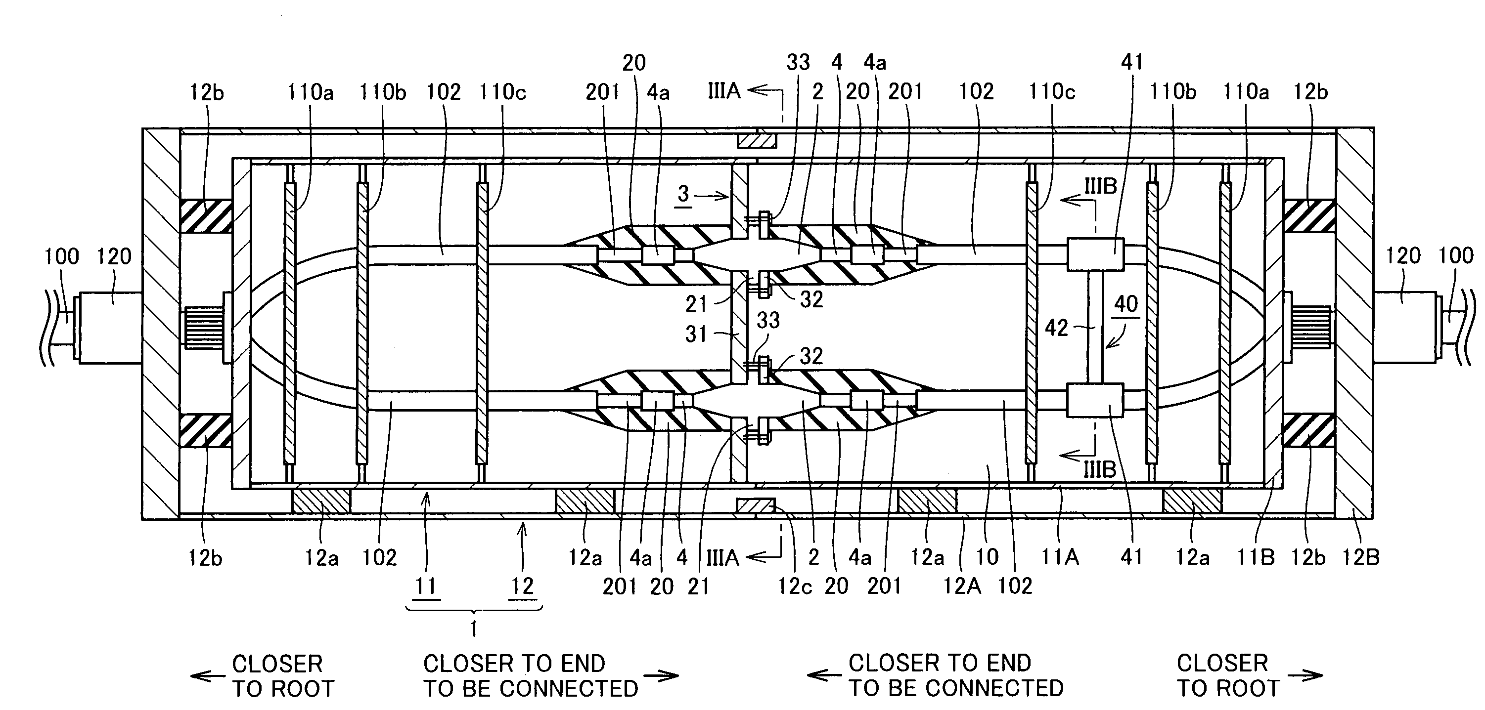
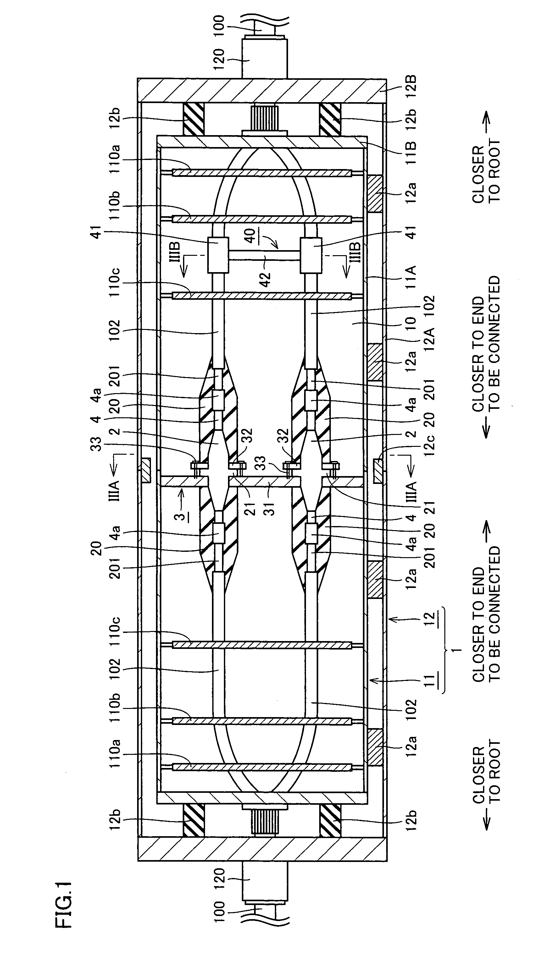
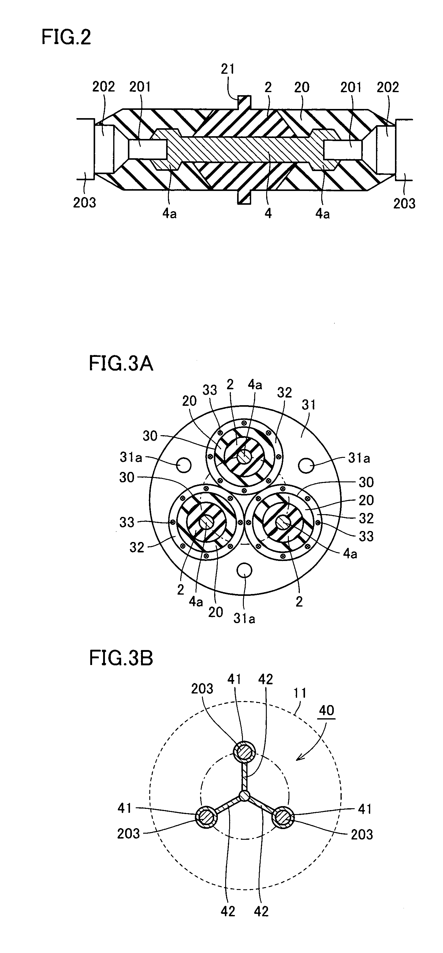
[0045]FIG. 1 shows an intermediate connection structure for a multiphase superconducting cable including a plurality of cable cores 102 having superconductor. In the present embodiment it shows a 3-phase superconducting cable 100 having three cable cores 102 assembled in one unit. While FIG. 1 is a side view and accordingly shows only two cores, as seen in a direction of a plane, as shown in FIG. 3A described later, three cable cores can be seen.

[0046]This connection structure includes a connection box 1 accommodating three conductor connects connecting a superconductor 201 of a cable core 102 of each phase extracted from a pair of 3-phase superconducting cables 100, a solid insulation member 2 fixed to each conductor connects' circumference, and a metal flange 3 allowing solid insulation member 2 to be fixed to connection box 1.

[0047]—Superconducting Cable—

[0048]

[0049]Three-phase superconducting cable 100 of...


PUM

PropertyMeasurementUnit
outer circumferenceaaaaaaaaaa
melting pointaaaaaaaaaa

Abstract

A multiphase superconducting cable connection structure includes a connection box accommodating three conductor connects connecting a superconductor of a cable core of each phase extracted from a pair of 3-phase superconducting cables, a solid insulation member fixed to an outer circumference of each conductor connect, and a metal flange fixing the solid insulation member to the connection box. By fixing the metal flange to the connection box (a refrigerant vessel), the conductor connect can be positioned and the conductor connector's movement caused as the cable core thermally contracts can be reduced. The structure can help to position the conductor connect in the connection box and reliably hold it at a prescribed position.

Description

BACKGROUND OF THE INVENTION[0001]1. Field of the Invention[0002]The present invention relates generally to structures for connection of a multiphase superconducting cable including a plurality of cable cores having superconductor, and multiphase superconducting cable lines including the structure, and particularly to such structures capable of positionally stabilize a conductor connect in a connection box, and such lines including the structure.[0003]2. Description of the Background Art[0004]As one of superconducting cables that have been produced using a superconductor formed of a bismuth (Bi)-based high-temperature superconducting tape for example, not only a single-phase cable including a single cable core but a multiphase superconducting cable of multicore type that is produced by assembling a plurality of cable cores into one unit is also under development. FIG. 6 shows a 3-phase superconducting cable of 3-core type in cross section. With reference to the figure, this supercond...

Claims


Application Information

Patent Timeline
Patent Type & Authority Patents(United States)
IPC IPC(8): H01B12/00H01B12/02H01R4/68H02G15/115H02G15/34
CPCH01R4/68H02G15/34Y10S505/925Y02E40/648Y02E40/60
Inventor ASHIBE, YUUICHIMASUDA, TAKATOTAKAHASHI, YOSHIHISAMATSUO, KIMIYOSHIHONJO, SHOICHIMIMURA, TOMOO
Owner SUMITOMO ELECTRIC IND LTD
Why Eureka
Try Eureka