Powerline pulse position modulated transmitter apparatus and method

a technology of pulse position and transmitter, which is applied in the direction of electric controllers, ignition automatic control, instruments, etc., can solve the problems of complex and expensive retrofitting into an existing home, inconvenient operation, and connection between the controller and the lighting load

Inactive Publication Date: 2007-09-04
POWERLINE CONTROL SYST
View PDF8 Cites 36 Cited by
  • Summary
  • Abstract
  • Description
  • Claims
  • Application Information

AI Technical Summary

Benefits of technology

[0011]It is a further purpose and advantage of this invention to provide a method and apparatus for powerline pulse transmission wherein the voltage zero crossing is sensed and the communication signal pulse is transmitted and sensed in a receiver based on the signal position relative to either the zero crossing point or the position of one or more of the previous transmitted pulses.
[0012]It is a further purpose and advantage of this invention to provide a method and apparatus by a powerline pulse position modulation transmission method for the purpose of remote electrical load control.
[0013]It is a further purpose and advantage of this invention to provide a method and apparatus wherein the voltage zero crossing is sensed, and digital pulse windows are defined with respect to the zero voltage crossing, but spaced from the zero voltage crossing

Problems solved by technology

Normally, people do not make such changes because it is inconvenient to do so.
The problem is the connection between the controller and the lighting load.
Such connection may be hard-wired, but such is complex and very expensive to retrofit into an existing home.
Another connection system may operate at radio frequency, but this has proven difficult to implement because the FCC requires low signal levels which are subject to interference and because the transmission and receiving circuitry is complex and expensive.
Prior powerline communication schemes have had difficulties employing the powerline as a communication channel because the communication signals after being attenuated by the powerline circuitry

Method used


Image

  • Powerline pulse position modulated transmitter apparatus and method
  • Powerline pulse position modulated transmitter apparatus and method
  • Powerline pulse position modulated transmitter apparatus and method

Examples


Embodiment Construction

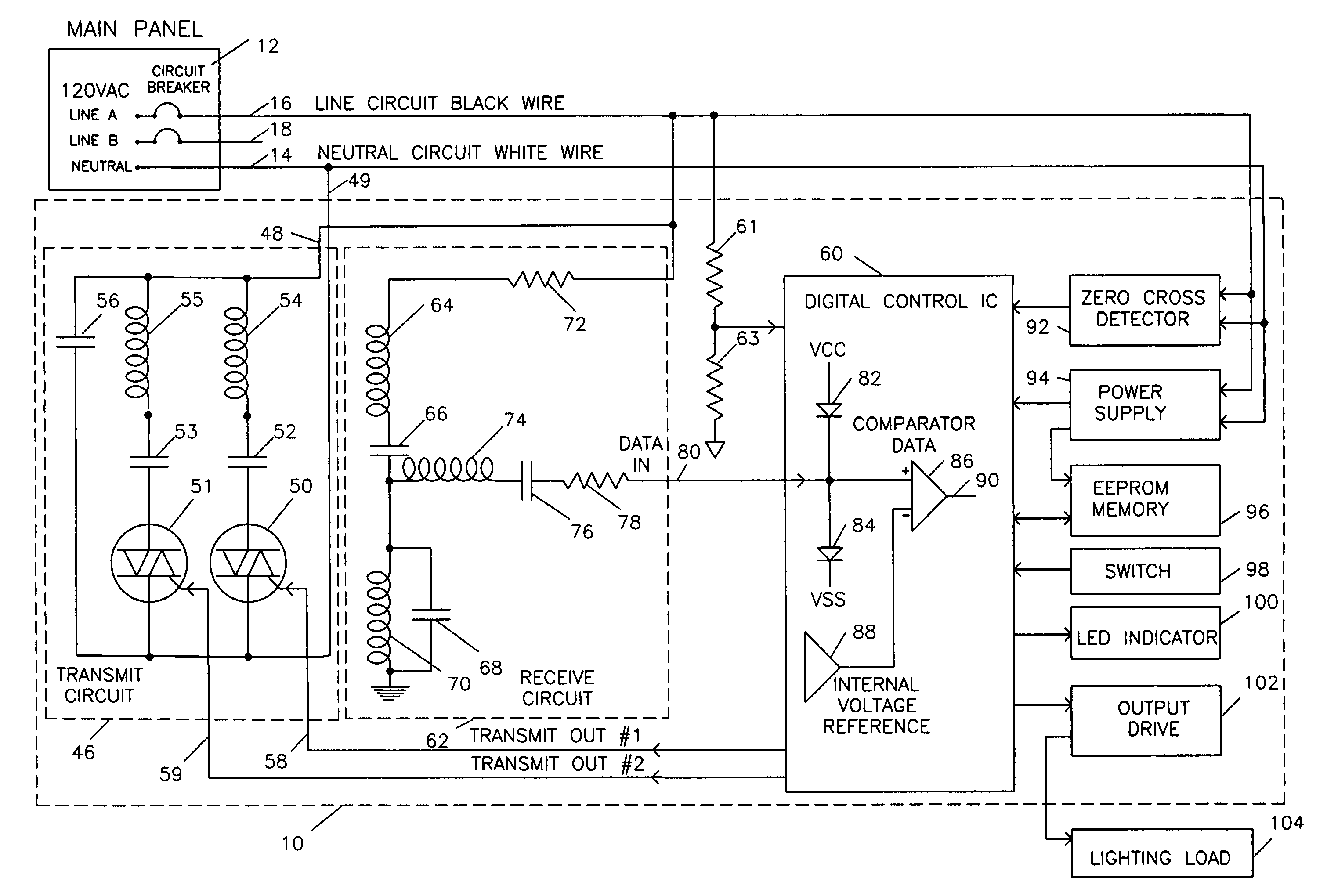
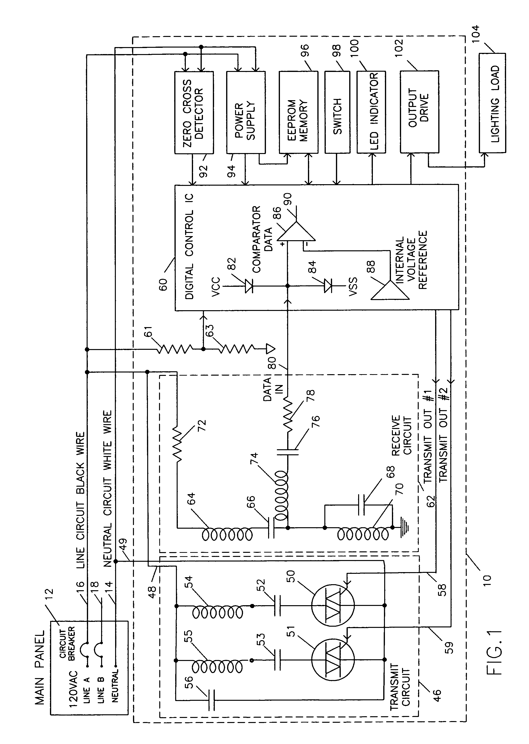
[0025]The purpose of the powerline pule position modulated communication transmitter apparatus of this invention as shown in FIG. 1 is to enable the communication of digital data from one device to another by means of the powerline to which both devices are connected. A further purpose is to enable communication with appliances and to control lighting or other electrical loads in one or more rooms of a residence.

Application Example Lighting Control System

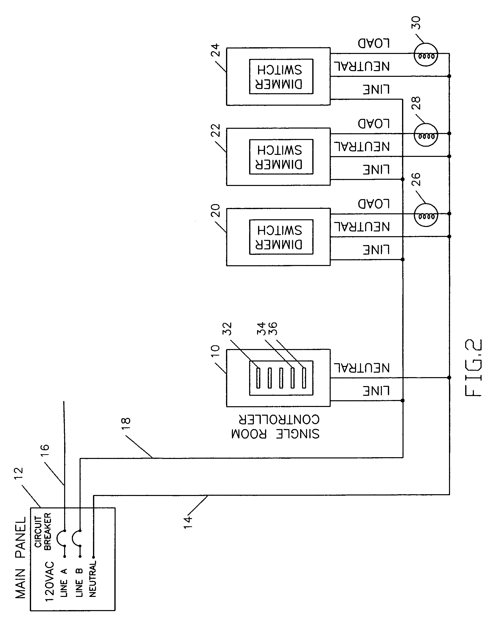
[0026]A lighting control system as shown in FIG. 2 and FIG. 3 will be used as an example of an application in this description of this invention.

[0027]In FIG. 2, transmitting controller 10 is supplied with conventional household electric power from circuit panel 12. Circuit panel 12 is supplied from commercial powerline and has two or three outputs. In the present example, the circuit panel 12 has a neutral line 14 and powerlines 16 and 18. Further, the powerlines 16 and 18 inside a domestic residence are derived from a center tappe...


PUM


Abstract

A transmitting controller is connected to a powerline and on command places a reference signal and a series of signal pulses in the powerline at a series of signal timing positions related to zero voltage crossing points so that the signals pulses are substantially in the powerline temporal quiet zone near zero crossing. The signal pulses are produced from a pair of capacitors and switches which are each sequentially charged a first polarity from the powerline and is discharged in the powerline at the opposite polarity so that the powerline voltage at the time of the pulse is additive to the pulse voltage. The receiving controller is connected to the powerline and has a filter circuit therein which filters away the powerline AC signal and noise to leave the reference and signal pulses. The signal pulses are compared to the position of starting reference pulses to determine in which signal timing position the pulses have occurred.

Description

CROSS-REFERENCE[0001]This invention is related to my prior applications, entitled “ZERO CROSSING BASED POWERLINE PULSE POSITION MODULATED COMMUNICATION SYSTEM”, application Ser. No. 09 / 656,160, filed Sep. 6, 2000, now U.S. Pat. No. 6,734,784, granted May 11, 2004; and “SYNCHRONIZATION REFERENCE PULSE BASED POWERLINE PULSE POSITION MODULATED COMMUNICATION SYSTEM,” filed Jun. 6, 2001, application Ser. No. 09 / 879,874, now U.S. Pat. No. 6,784.790, granted Aug. 31, 2004. This application relies for priority upon my prior Provisional Application 60 / 564,499 entitled “POWERLINE PULSE POSITION MODULATED TRANSMITTER APPARATUS AND METHOD,” filed Apr. 22, 2004.FIELD OF THE INVENTION[0002]This invention is directed to an apparatus which enables the transmission of digital communication between two or more devices wherein the devices are connected to the same powerline and use the same powerline to receive power and as a physical channel for electronic intercommunication.BACKGROUND OF THE INVENTI...

Claims


Application Information

Patent Timeline
IPC IPC(8): G08B3/00
CPCH02J13/0024H05B37/0263Y02B70/3283Y04S20/246H02J13/00009H05B47/185Y02B70/30
Inventor LESTER, MARSHALL E.
Owner POWERLINE CONTROL SYST
Why Eureka
Try Eureka