Method and system for sensor signal fusion

a sensor signal and signal fusion technology, applied in anti-collision systems, amplifier modifications to reduce noise influence, position fixation, etc., can solve the problems of vehicle wasting additional computational resources, output data may suffer from false positives of the presence of obstacles, and slow down

Active Publication Date: 2007-09-04
DEERE & CO
View PDF20 Cites 136 Cited by
  • Summary
  • Abstract
  • Description
  • Claims
  • Application Information

AI Technical Summary

Benefits of technology

[0003]A system and a method for conducting sensor fusion supports reliable determinations of objects and obstacles around a vehicle based on filtered sensor inputs from multiple sensors. The first sensor collects a first group of first sensor readings of first size. A second sensor collects a second group of second sensor readings of second size. A reference frame manager references the first group and the second group of readings to a vehicle coordinate reference frame. An integration module establishes a composite grid referenced to the vehicle coordinate reference frame or the ground based on a spatially and temporally aligned integration of the readings of the first group and the second group. An update module refreshes the composite grid upon material movement of the vehicle such that the overall state (e.g., occupancy) of each cell in the composite grid varies in accordance with the particular location of the vehicle in the environment.

Problems solved by technology

If radar or sonar systems are individually used to provide a signal that represents the positions of obstacles near a vehicle, the output data may suffer from false positives of the presence of obstacles because of noise and clutter or misdetections because of the reflectivity and relative aspect of the obstacles with respect to the vehicle.
If false positives of obstacles are present, the vehicle may expend additional computational resources in obstacle avoidance or may stop or slow down unnecessarily interfering with the efficient execution of a mission.

Method used


Image

  • Method and system for sensor signal fusion
  • Method and system for sensor signal fusion
  • Method and system for sensor signal fusion

Examples


Embodiment Construction

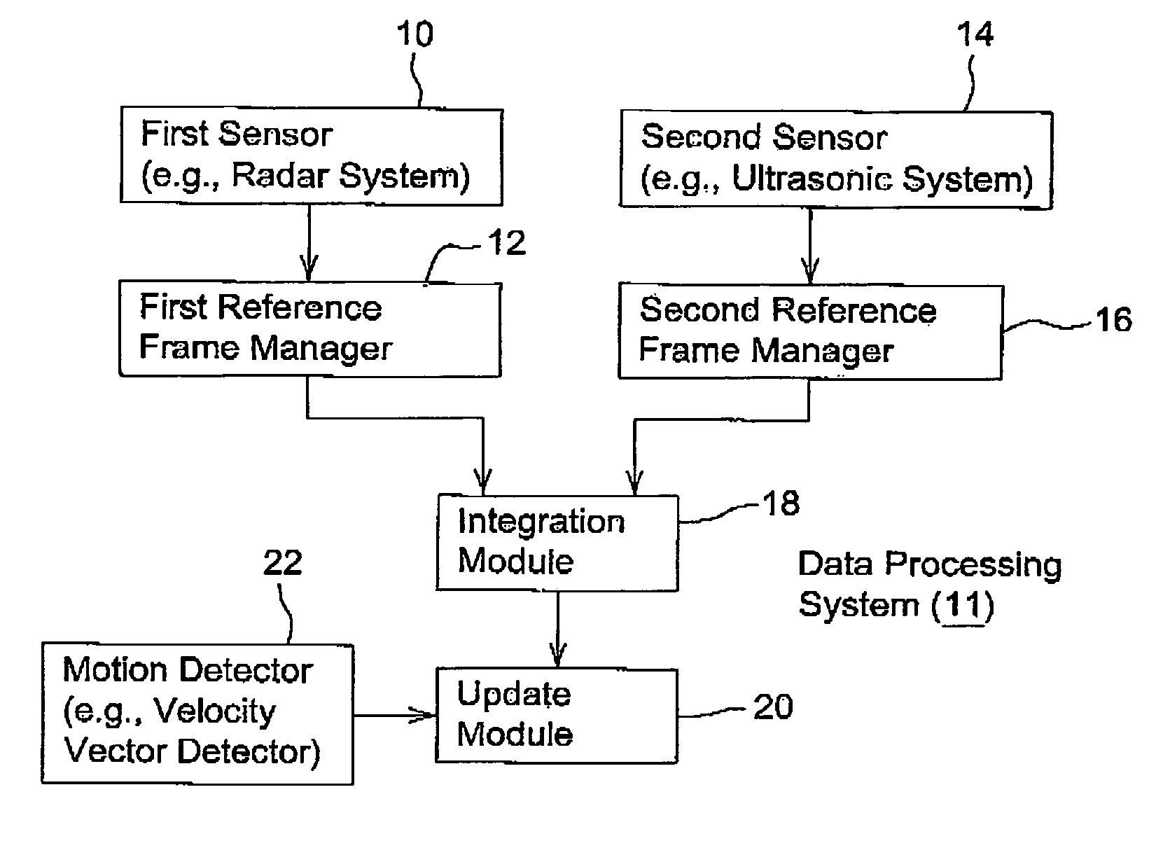
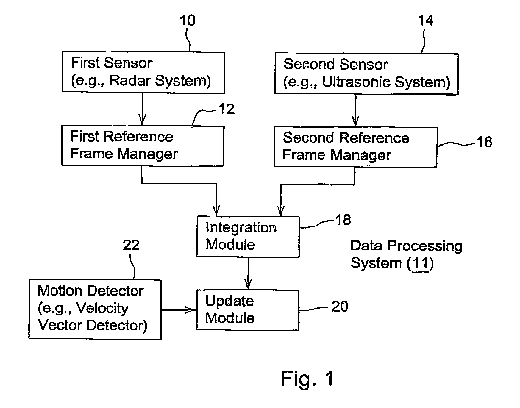
[0012]In accordance with one embodiment of the invention, the data processing system 11 of FIG. 1 comprises a first sensor 10 coupled to a first reference frame manager 12 and a second sensor 14 coupled to a second reference frame manager 16. In turn, the first reference frame manager 12 communicates to an integration module 18; the second reference frame manager 16 communicates to the integration module 18. The integration module 18 and a motion detector 22 provide input data to an update module 20. The data processing system 11 is associated with or mounted on a vehicle.

[0013]In one illustrative configuration, the first sensor 10 comprises a radar system, whereas the second sensor 14 comprises an ultrasonic system. However, the first sensor 10, the second sensor 14, or both may comprise any suitable distance sensor or range finder. The first sensor 10 and the second sensor 14 each provide a data output or an output signal that is indicative of the distance (e.g., range) between th...


PUM


Abstract

The first sensor collects a first group of first sensor readings of first fixed size dependent on a range of a first sensor and safeguarding requirements of a vehicle. A second sensor collects a second group of second sensor readings of second fixed size dependent on a range of a second sensor and the safeguarding requirements. A reference frame manager references the first group and the second group of readings to a vehicle coordinate reference frame. An integration module establishes a composite grid referenced to the ground based on a spatially aligned integration of the readings of the first group and the second group. A update module refreshes the composite grid upon material movement of the vehicle such that the global occupancy of each cell in the composite grid varies in accordance with the particular location of the vehicle on the terrain.

Description

FIELD OF THE INVENTION[0001]This invention relates to a method and system for sensor signal fusion.BACKGROUND OF THE INVENTION[0002]If radar or sonar systems are individually used to provide a signal that represents the positions of obstacles near a vehicle, the output data may suffer from false positives of the presence of obstacles because of noise and clutter or misdetections because of the reflectivity and relative aspect of the obstacles with respect to the vehicle. If false positives of obstacles are present, the vehicle may expend additional computational resources in obstacle avoidance or may stop or slow down unnecessarily interfering with the efficient execution of a mission. Thus, there is a need to combine information from multiple sensors to improve the accuracy in the detection of the presence or absence of obstacles around a vehicle. Further, there is need to make the combined information available even when the absolute or global position of the vehicle is not known ...

Claims


Application Information

Patent Timeline
Patent Type & Authority Patents(United States)
IPC IPC(8): G01S5/00G06F17/00G06F17/10
CPCG01S13/723G05D1/0257G01S13/862G05D1/027G05D1/0272G05D1/0274G05D1/0278G05D1/028
Inventor FOESSEL, ALEX DIETRICH
Owner DEERE & CO
Why Eureka
Try Eureka