Method of continuously fabricating a corrugated coaxial cable

a technology of coaxial cable and continuous fabrication, which is applied in the direction of insulating conductor/cable, shape tools, applications, etc., can solve the problems of poor quality, too complex operation for excellent efficiency to be likely, and nevertheless suffer from certain drawbacks, so as to reduce scrap and defects, the effect of high fabrication speed and no risk of degrading quality

Inactive Publication Date: 2007-09-11
ACOME SOC COOP & PARTICIPATIVE COOP DE PRODION A CAPITAL VARIABLE
View PDF18 Cites 11 Cited by
  • Summary
  • Abstract
  • Description
  • Claims
  • Application Information

AI Technical Summary

Benefits of technology

[0013]An object of the present invention is thus to remedy those numerous drawbacks by providing a method that is more stable and easier to adjust while also making it possible to envisage higher speeds of fabrication without any risk of degrading quality, and simultaneously reducing scrap and defects due to fabrication drift.
[0014]The invention also makes it easier to perform certain operations in tandem such as making the dielectric or the sheathing.
[0015]The present invention thus seeks to provide greater stability and increased productivity so as to make it possible to increase speeds.

Problems solved by technology

Although known methods do indeed enable high quality products to be made that are widely available, they nevertheless suffer from certain drawbacks.
Under those circumstances it will be understood that changing a single parameter requires all of the other parameters to be changed in order to conserve the desired dimensioning, which means firstly that operation is too complex for excellent efficiency to be likely, and secondly that there are numerous risks of malfunction which lead either to poor quality or else to additional production going to scrap.
Unfortunately, this curvature is not uniform and changes as the reel unwinds, which means that this cable element is naturally of unstable position at the time it is inserted into the peripheral conductor.
Furthermore, irregular distribution of the dielectric on the upstream reel is transferred directly to the corrugator in terms of varying tension that gives rise to variation in the shape of the corrugations.
(Some existing methods do not even include the operating flexibility provided by the corrugating head having a floating mount which can be used to regulate the speed of rotation of the corrugating head.)
In all cases, existing methods are thus methods of making high quality cables but at the cost of great difficulty in terms of controlling and governing the method, and requiring vigilance that is poorly compatible with certain modern production requirements, and speeds that are very limited.
Finally, it also follows that efficiency is fairly bad due either to time required for adjustment purposes or to lengthy readjustments requiring operations that are difficult, or else to reject rates that are rather high due in particular to drift in performance.

Method used


Image

  • Method of continuously fabricating a corrugated coaxial cable
  • Method of continuously fabricating a corrugated coaxial cable
  • Method of continuously fabricating a corrugated coaxial cable

Examples


Embodiment Construction

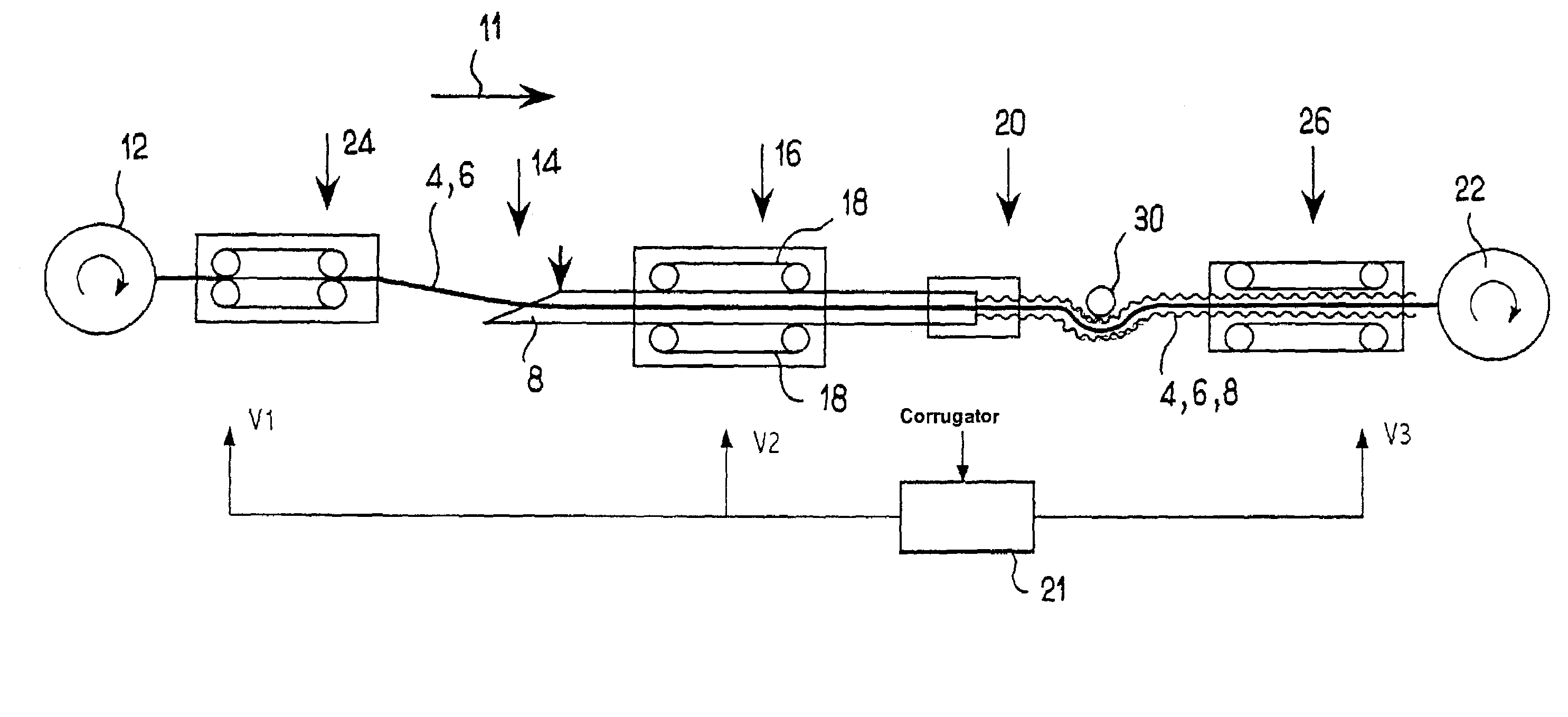
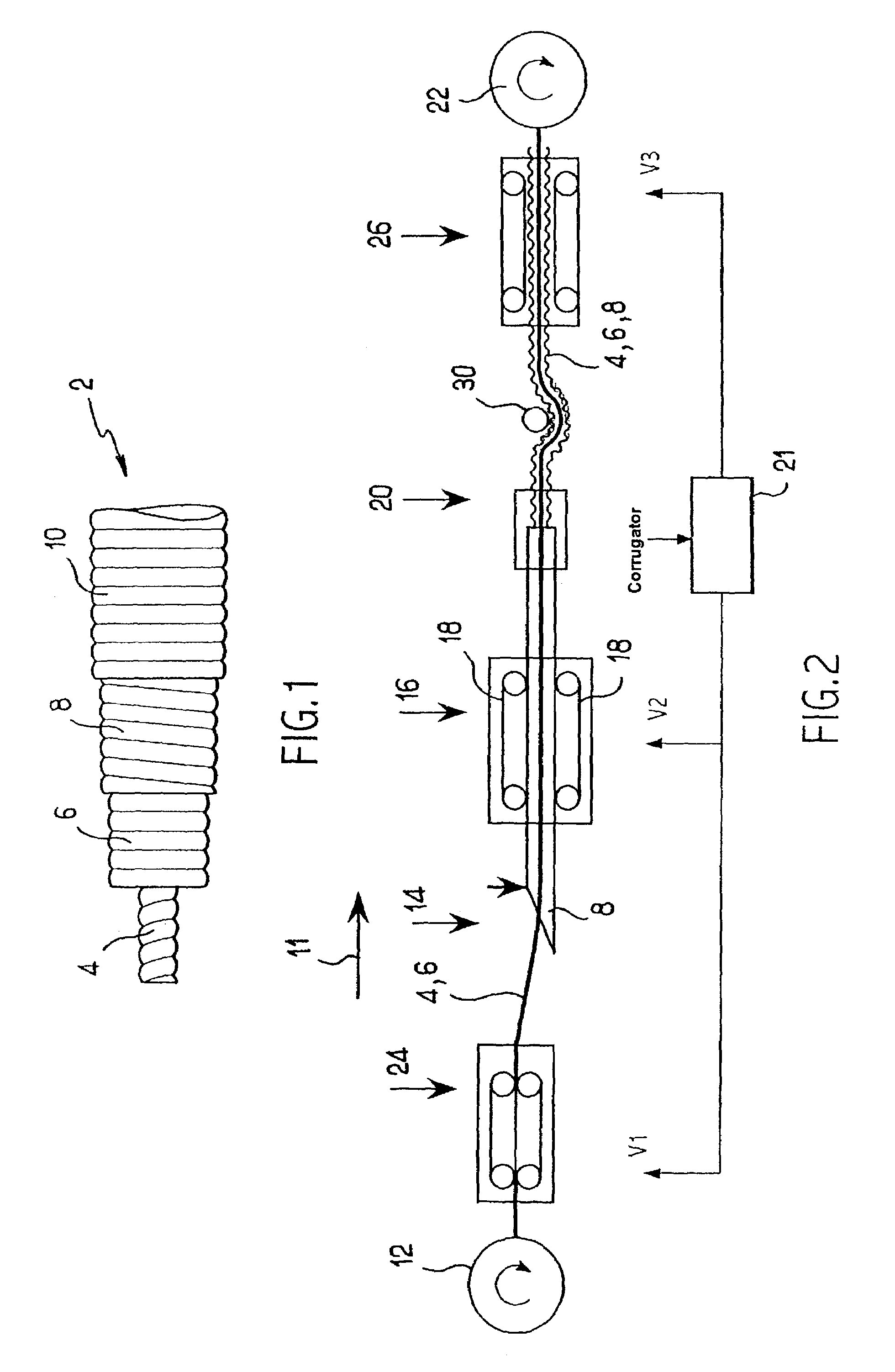
[0060]In the embodiments described below, the method of the invention seeks to fabricate a corrugated coaxial cable 2 as shown, for example, in FIG. 1. The cable comprises a metal central conductor 4 constituting the core of the cable. The cable comprises dielectric material 6 in the form of a cylindrical tube covering the central conductor 4. In this case the dielectric is constituted by an expanded and extruded polymer. The cable further comprises a peripheral conductor 8 in the form of a cylindrical tube covering the dielectric material 6. Finally, the cable comprises a sheath 10 of polymer material in the form of a cylindrical tube covering the peripheral conductor 8. The layers 4, 6, 8, and 10 follow one another directly in that order going radially outwards from the central axis of the cable. Such a structure is conventional and is not described in further detail herein.

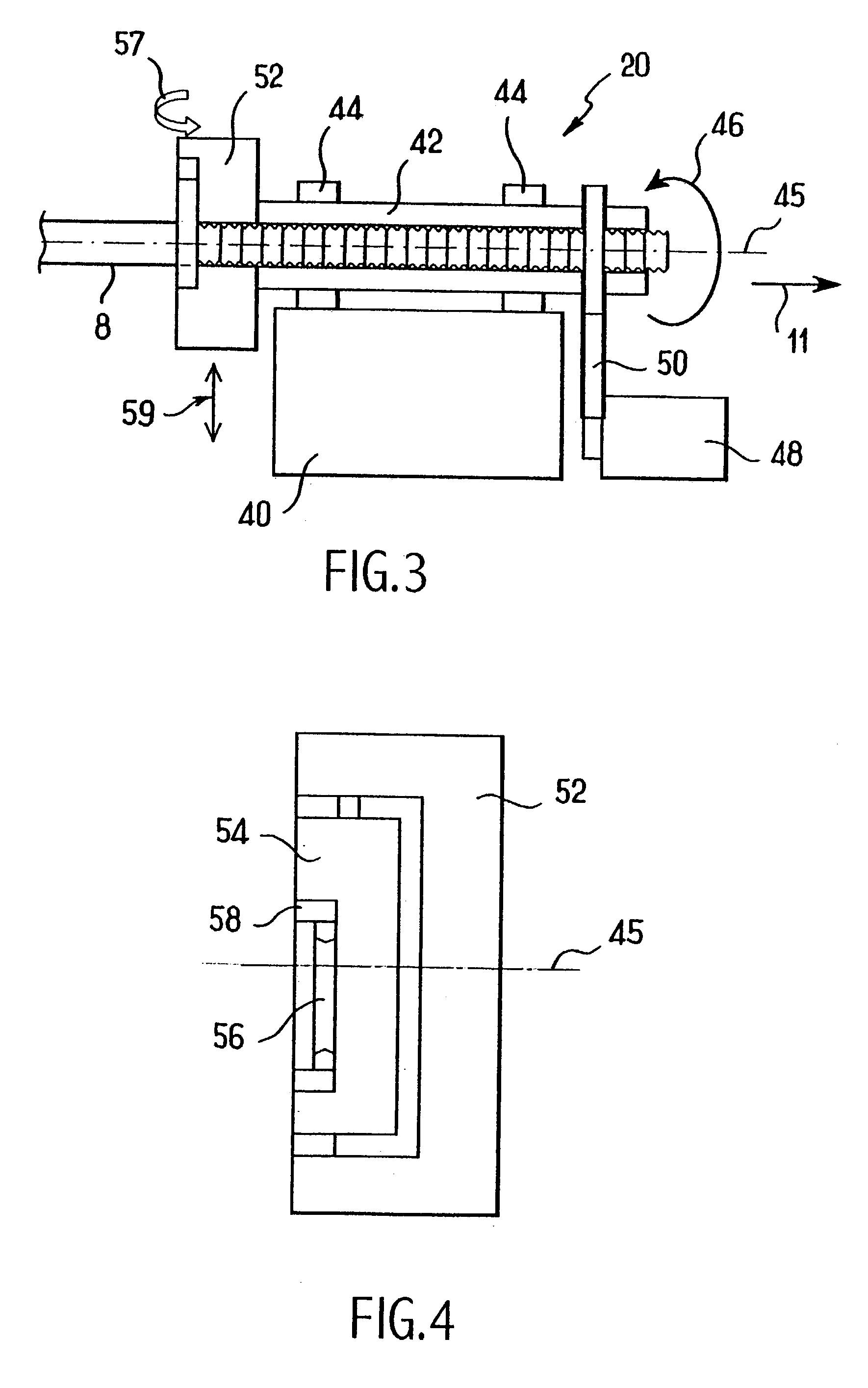
[0061]The peripheral conductor 8 is corrugated in conventional manner so as to give the cable a degree of fl...


PUM

PropertyMeasurementUnit
constant speedaaaaaaaaaa
speedaaaaaaaaaa
upstream speedaaaaaaaaaa

Abstract

The invention relates to a method of continuously fabricating a coaxial cable in which ring-shaped corrugations are imparted to a conductor of the cable in a corrugator. The corrugator is made to operate at constant speed.

Description

[0001]The present invention relates to a method of fabricating a corrugated coaxial cable.BACKGROUND OF THE INVENTION[0002]Coaxial cables are nowadays in widespread use for numerous applications, and in particular for transmitting signals at radio frequency. For example, such cables are known for conveying television signals or telephone signals for various generations of cellular telephones.[0003]A coaxial cable comprises a central conductor surrounded by a dielectric and by a peripheral conductor which is generally protected by a polymer sheath. In many cases, the dielectric is constituted by an expanded and extruded polymer, and the peripheral conductor is made of copper or of aluminum. In numerous cases, the peripheral conductor is corrugated so as to give the coaxial cable flexibility that is compatible with conditions during installation while nevertheless guaranteeing the best possible transmission qualities.[0004]It is well known that these transmission qualities depend both...

Claims


Application Information

Patent Timeline
Patent Type & Authority Patents(United States)
IPC IPC(8): H01B13/20H01B13/00
CPCH01B13/0009Y10T29/49117Y10T29/49123
Inventor ESTIENNE, THIERRYBESNIER, GÉRARDDUC, JEAN-PAUL
Owner ACOME SOC COOP & PARTICIPATIVE COOP DE PRODION A CAPITAL VARIABLE
Why Eureka
Try Eureka