Chipper bed knife

a technology of chipping bed and knife, which is applied in the direction of wood turning machine, flat surface machine, cocoa, etc., can solve the problems of chipping screen, conveyor and other equipment, and the outermost layer of the debarked log is often difficult to cu

Inactive Publication Date: 2007-09-11
ANDRIZ OY
View PDF18 Cites 11 Cited by
  • Summary
  • Abstract
  • Description
  • Claims
  • Application Information

AI Technical Summary

Benefits of technology

[0004]The object of the invention is to provide a bed knife by means of which the wood strips can be cut to such a length that they will not cause problems in the further processing of the chips.
[0007]The bed knife can be one solid piece or, alternatively, of two or more pieces joined together. The bed knife according to the invention can thus easily replace a conventional bed knife.

Problems solved by technology

The outermost layer of a debarked log is often difficult to cut, as a result of which the said long strips are produced.
Such wood strips pass through between the chipper disc and bed knife without being cut, thus causing problems at chip screens, conveyors and other equipment.

Method used


Image

  • Chipper bed knife
  • Chipper bed knife
  • Chipper bed knife

Examples


Embodiment Construction

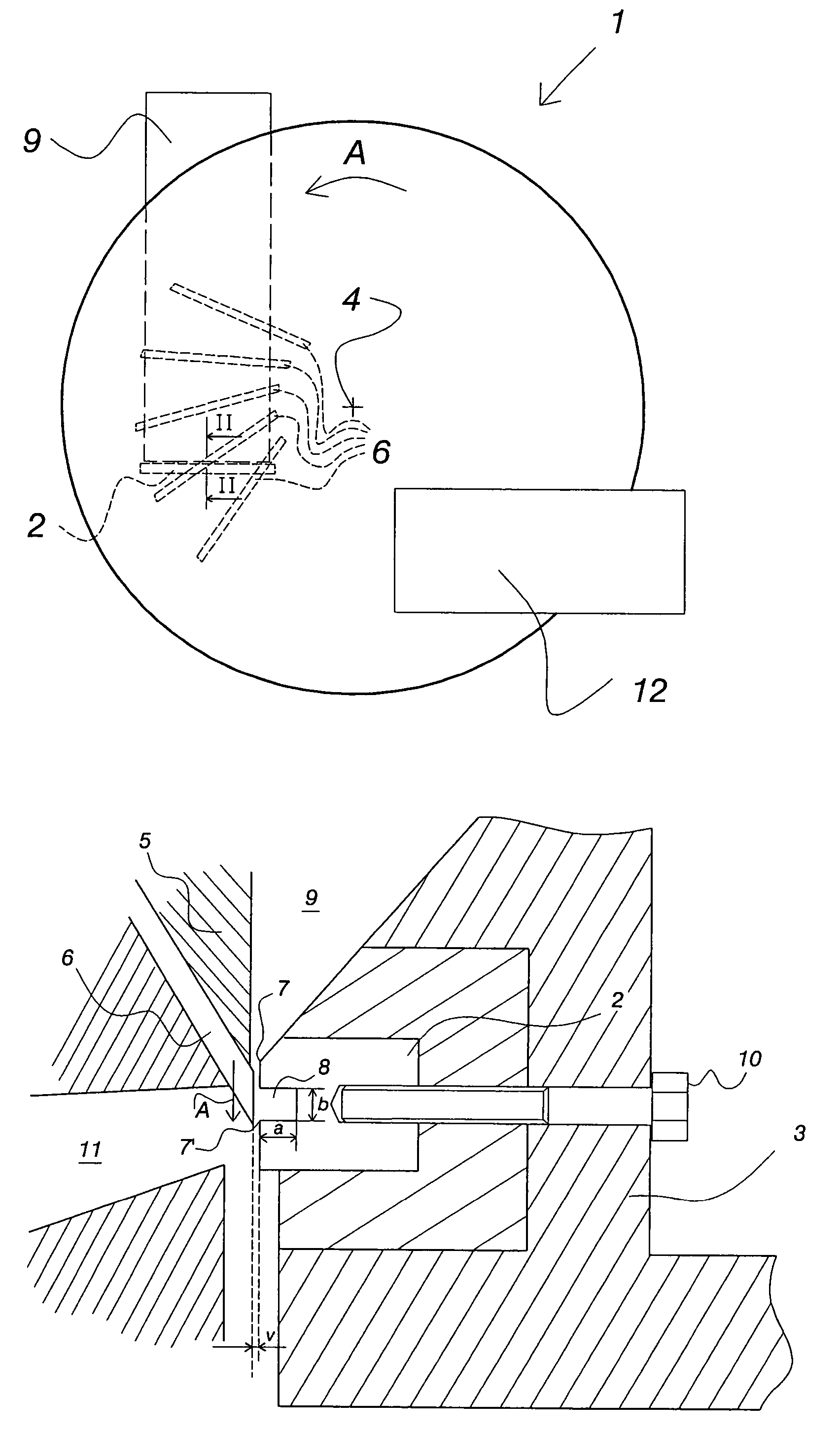
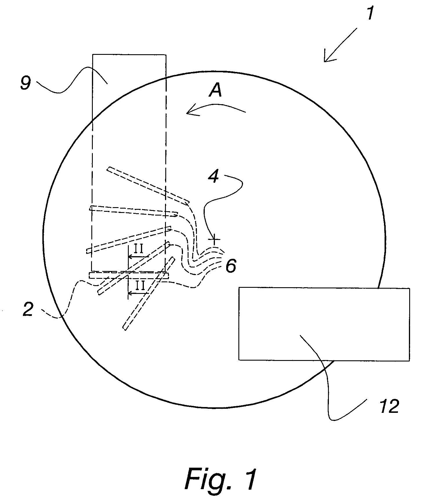
[0013]A disc chipper 1 is generally used when producing wood chips for the needs of the pulp and paper industry, a schematic example of which is shown in FIG. 1. The wood is chipped by knives 6 fitted to the chipper disc 5 usually slightly deviating from the radial direction. For the sake of clarity, however, only a few of these knives 6 are presented in FIG. 1. The knives 6 of the chipper disc 5 hit the log to be chipped, which leans against the bed knife 2 on its opposite side. The bed knife 2 is fitted to the end of the log infeed chute 9.

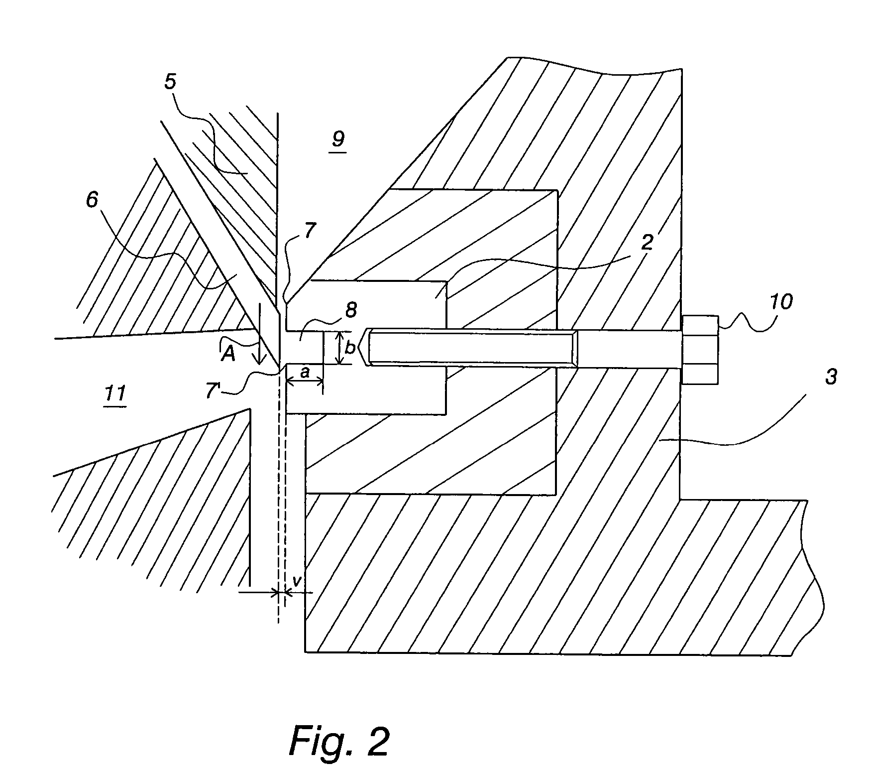
[0014]The bed knife 2 of the chipper 1 is attached to the chipper 1 frame 3 detachably, for example, by means of bolts 10. The chipper disc 5 is supported on its shaft 4, which shaft is fitted rotatably to the frame 3. The chipper disc 5 comprises a number of knives 6, which are arranged to pass the knife edge 7 of the bed knife 2 at a distance corresponding to the required knife clearance v, when the chipper disc 5 is rotating in the direction ...


PUM


Abstract

The invention relates to a chipper (1) bed knife (2) attached detachably to the chipper frame (3), the chipper (1) having a chipper disc (5) supported on its shaft (4), which shaft is fitted rotatably to the chipper frame (3), the chipper disc (5) comprising a number of knives (6) arranged to pass the knife edge (7) of the bed knife (2) at a distance corresponding to the required knife clearance (v), when the chipper disc (5) is rotating. The bed knife (2) also has a second knife edge (7′), the said knife edges (7, 7′) being arranged at a distance from each other in the direction of movement (A) of the chipper disc (5) knives (6). A groove (8) is formed in the bed knife (2) between the said knife edges (7, 7′).

Description

CROSS REFERENCE TO RELATED APPLICATIONS[0001]This application is a Continuation-in-Part of International Application No. PCT / FI2004 / 050024, filed Mar. 8, 2004, designating the US and claims the benefit under 35 U.S.C. §119 of Finnish Patent Application No. 20035051, filed Apr. 24, 2003.BACKGROUND OF THE INVENTION[0002]The invention relates to a chipper bed knife that is selectively detachably to the chipper frame, the chipper having a chipper disc supported on its shaft, which shaft is fitted rotatably to the chipper frame.[0003]Such a chipper disc is comprised of a number of knives arranged to pass the knife edge of the bed knife at a distance corresponding to the required knife clearance, when the chipper disc is rotating. When logs are chipped, very thin and long strips are sometimes cut off. This is due to the properties of wood. The outermost layer of a debarked log is often difficult to cut, as a result of which the said long strips are produced. Such wood strips pass through ...

Claims


Application Information

Patent Timeline
Patent Type & Authority Patents(United States)
IPC IPC(8): B27C7/00B02C18/18B27L11/00
CPCB02C18/18B27L11/005
Inventor OLOFSSON, ANDERS
Owner ANDRIZ OY
Why Eureka
Try Eureka