Method of joining dissimilar materials

Inactive Publication Date: 2007-09-11
GM GLOBAL TECH OPERATIONS LLC +1
View PDF12 Cites 39 Cited by
  • Summary
  • Abstract
  • Description
  • Claims
  • Application Information

AI Technical Summary

Benefits of technology

[0010]In a preferred embodiment of the invention, the electrode for contact with the rivet head is used like a hammer to drive the rivet through the first component into the wall of the second component, and the counter-electrode on the opposite side of the second component is used like an anvil to hold the second component against the impact of the self-piercing rivet. The counter-electrode is shaped, if necessary, to conform to a contour in the second component so as to better serve both the anvil function and electrical contact function of that electrode.

Problems solved by technology

But since the second component may be an elongated hollow body, there may be no access to the buried end of the rivet shank to form it over against the inside of the wall of the second component to secure a riveted joint.

Method used


Image

  • Method of joining dissimilar materials
  • Method of joining dissimilar materials

Examples


Embodiment Construction

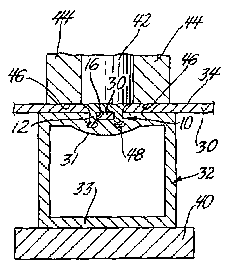
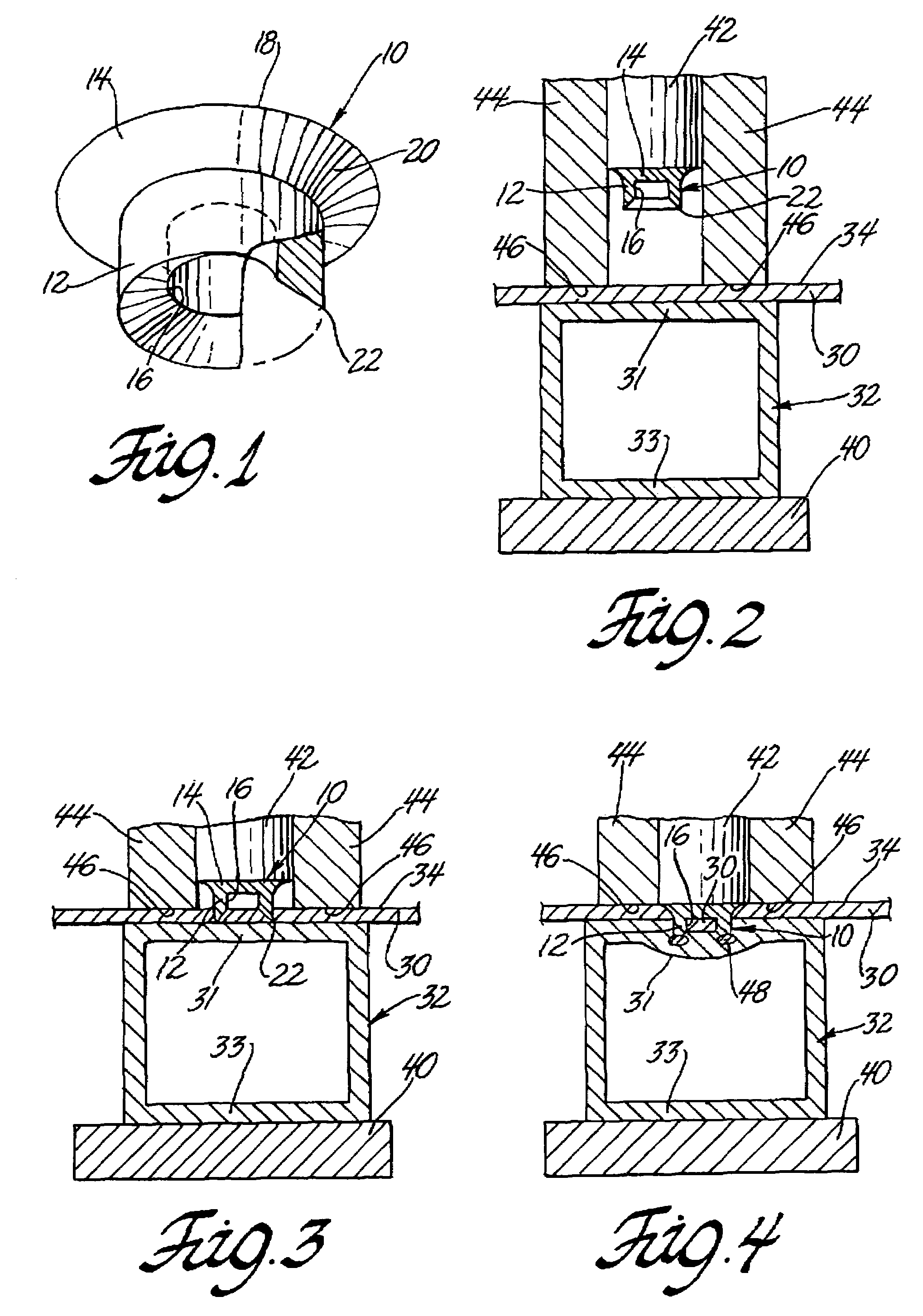
[0017]The present invention generally provides a method of joining dissimilar materials, such as a non-ferrous component to a ferrous component. More specifically, the present invention provides a method of joining a non-ferrous sheet-metal component to a ferrous metal tube, such as for use in automotive body assemblies. The present invention also contemplates the reverse scenario wherein a method is provided for joining a ferrous sheet metal component to a non-ferrous metal tube. The method of this invention uses features of self-piercing riveting practices and resistance spot welding methods to provide an improved method for joining dissimilar materials, which is particularly well suited to welding a sheet metal component to a tube with only single-sided access to the joining location. The present invention, however, also contemplates that the ferrous and non-ferrous components may be attached using only a weld joint, rather than the combination of a weld joint and mechanical fast...


PUM

PropertyMeasurementUnit
diameteraaaaaaaaaa
diameteraaaaaaaaaa
electrical currentaaaaaaaaaa

Abstract

The present invention provides a method of joining dissimilar materials, particularly a non-ferrous component to a ferrous component to form an assembly. In an overlapping configuration, the parts are held together under a clamping force while a self-piercing rivet is driven through the assembly by a welding electrode. The rivet pierces and passes through the non-ferrous component and then at least into contact with the ferrous component to thereby form a mechanical interlock. An electrical current is then applied to this mechanical retention to melt a portion of the rivet as well as a portion of the ferrous metal in the joining region. The flow of electrical current is then stopped after several welding cycles where the now melted material is allowed to solidify upon cooling, thereby forming a weld.

Description

TECHNICAL FIELD[0001]This invention relates to a method of joining dissimilar materials. More specifically, the invention relates to a joining method in which a first material is attached to a second material using a penetrating welding member therebetween, wherein a welding current is momentarily passed through the welding member to fuse the welding member to the second material and thereby trap the first material therebetween.BACKGROUND OF THE INVENTION[0002]Shaped metal tubes are desirable for use in automotive body assemblies due to their strength and relatively low weight. In constructing automotive body assemblies that use bent, hydroformed tubes or the like, it is sometimes necessary to join a body member to a structural tube, wherein the body member is composed of a first material and the structural tube is composed of a dissimilar, second material.[0003]However, it is often difficult to use traditional spot welding, riveting, or bolting practices to make sheet-to-tube assem...

Claims


Application Information

Patent Timeline
Patent Type & Authority Patents(United States)
IPC IPC(8): B29C65/00B21J15/00B32B37/00B32B7/04B23K11/00B23K11/20
CPCB23K11/0066B23K11/20Y10T29/49957Y10T29/49956
Inventor HOU, WENKAOHU, SHIXIN JACKWANG, PEI-CHUNG
Owner GM GLOBAL TECH OPERATIONS LLC
Why Eureka
Try Eureka