Phase-resolved measurement for frequency-shifting interferometry

a technology of frequency-shifting interferometry and phase resolution, which is applied in the field of frequency-shifting interferometry, can solve the problems of unambiguous frequency of phase change, and achieve the effects of improving accuracy, saving processing time, and expanding the range of unambiguous measuremen

Active Publication Date: 2007-09-11
CORNING INC
View PDF15 Cites 15 Cited by
  • Summary
  • Abstract
  • Description
  • Claims
  • Application Information

AI Technical Summary

Benefits of technology

[0024]Noise and other errors of a random or systematic nature can lower the correlation between the pixel intensity values and the predicted values of the periodic function. However, the pattern of localized peaks within the envelope of the generalized peak can still provide a good estimate of the optical path length differences among the different pixels of the interference patterns. Care is preferably taken for determining the measuring beam frequencies at which the pixel intensity data is gathered, so that high correlations can be made with the predicted values calculated at the same measuring beam frequencies.
[0027]Although for purposes of fitting the periodic function to the pixel intensity data sets, the measuring beam frequencies, if otherwise known, can be unevenly spaced, approximations of the surface height variations among the pixels can be made more readily by equally spaced measuring beam frequencies. Conventional Fourier transforms can be used to initially process the pixel intensity data sets to approximate the optical path length differences to within the generalized correlation envelope of the periodic function. The interim approximations can save processing time and serve other purposes such as distinguishing different measuring regions of the test surfaces.
[0028]However, for purposes of both improving accuracy and expanding the range of unambiguous measurement, the measuring beam frequencies can be unequally spaced, which is referred to as chirping. More closely spacing some of the measuring beam frequencies contributes to expanding the range of measurement, and more distantly spacing other of the measuring beam frequencies for enlarging the overall range of measuring beam frequencies contributes to raising the accuracy of measurement or to loosening tolerances for achieving desired accuracies.

Problems solved by technology

However, the frequency of phase change varies unambiguously within a wider range of optical path length differences up to the absolute optical path length difference between the interfering measuring beams.

Method used


Image

  • Phase-resolved measurement for frequency-shifting interferometry
  • Phase-resolved measurement for frequency-shifting interferometry
  • Phase-resolved measurement for frequency-shifting interferometry

Examples


Embodiment Construction

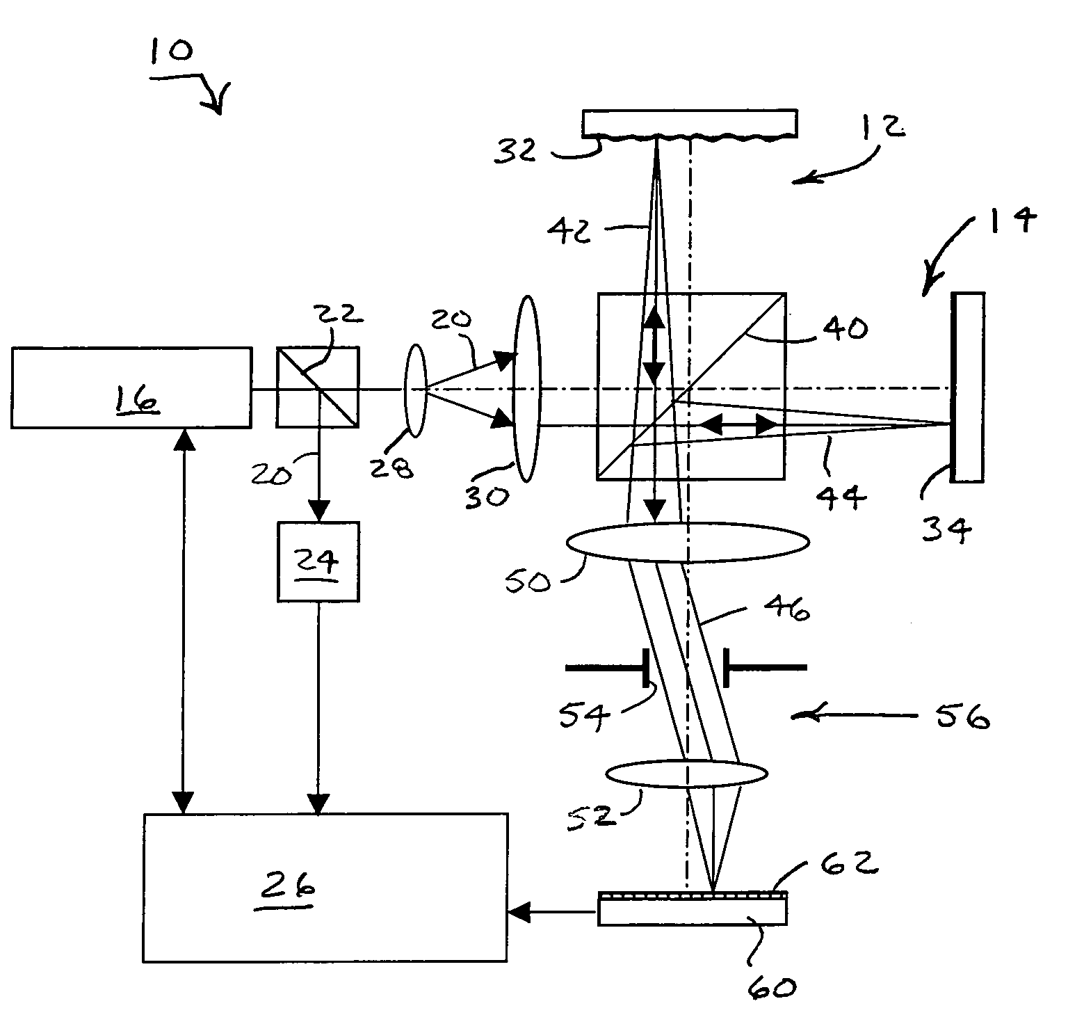
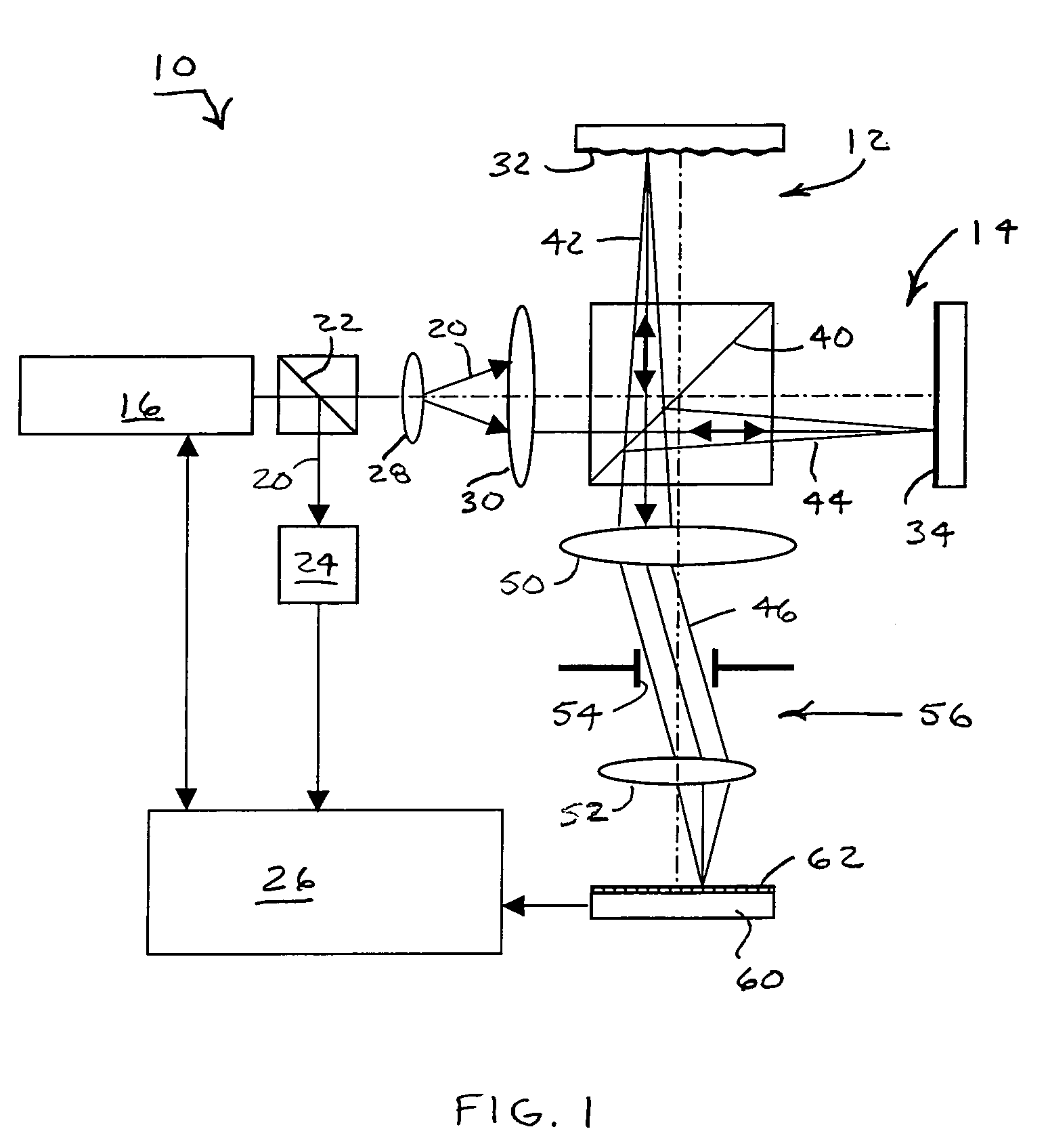
[0035]An image-based frequency-shifting interferometer 10 arranged in accordance with the invention is depicted in the configuration of a Michelson interferometer having separate test and reference arms 12 and 14. Other interferometer configurations including common test and reference arm configurations, such as a Fizeau interferometer, can also be used in the practice of the invention. Such interferometers preferably have the capability of producing and processing multiple interference patterns at different measuring beam frequencies.

[0036]For example, the illustrated interferometer 10 includes a frequency tunable laser 16 that emits a measuring beam 20 having a frequency that is adjustable through a range of discrete frequencies. A beamsplitter 22, which preferably has the form of a partial reflector, diverts a small percentage of the measuring beam 20 to a frequency analyzer 24. The measuring beam frequency is measured by the frequency analyzer 24, and the frequency information i...


PUM


Abstract

A frequency-shifting interferometer gathers intensity data from a set of interference patterns produced at different measuring beam frequencies. A periodic function is matched to the intensity data gathered from the set of interference patterns over a corresponding range of measuring beam frequencies. Localized correlations involving phase offsets between the interfering portions of the measuring beam are used to inform a determination of a rate of phase change with measuring beam frequency corresponding to the optical path length difference between the interfering beam portions.

Description

BACKGROUND OF THE INVENTION[0001]1. Field of the Invention[0002]The invention relates to frequency-shifting interferometry in which interferometric data is gathered at multiple measuring beam frequencies and to processing methods for exploiting relationships apparent from resulting interference patterns generated at the multiple measuring beam frequencies for measuring optical path length differences between interfering portions of the measuring beams.[0003]2. Description of Related Art[0004]Pixel intensities within interference fringe patterns produced by interfering beams vary in an orderly manner as a result of progressive changes in either optical path length difference between the measuring beams or measuring beam frequency. The pixel intensities progressively vary through cycles of constructive and destructive interference corresponding to modulo 2π phase differences between the interfering beams.[0005]Conventional phase-shifting interferometry, such as used for measuring surf...

Claims


Application Information

Patent Timeline
Patent Type & Authority Patents(United States)
IPC IPC(8): G01B9/02
CPCG01B9/02004G01B9/02079G01B9/02069G01B9/02002G01B2290/60G01R23/00G01R23/12
Inventor KULAWIEC, ANDREWMARRON, JOSEPH C.MCCLIMANS, DONTRONOLONE, MARK J.
Owner CORNING INC
Why Eureka
Try Eureka