Al technical title is built by PatSnap Al team. It summarizes the technical point description of the patent document.
a power converter, high-efficiency technology, applied in the direction of electric variable regulation, process and machine control, instruments, etc., can solve the problem of complicated task
Inactive Publication Date: 2007-09-11
BANK OF AMERICA NAT TRUST & SAVINGS ASSOC
View PDF43 Cites 67 Cited by
Summary
Abstract
Description
Claims
Application Information
AI Technical Summary
This helps you quickly interpret patents by identifying the three key elements:
Problems solved by technology
Method used
Benefits of technology
Problems solved by technology
The use of transistors as synchronous rectifiers in high switching frequency converters presents several technical challenges.
This task is made more complicated when the converter provides electrical isolation between its input and output because the synchronous rectifier drives are then isolated from the drives of the main, primary side transistors.
Another challenge is the need to minimize losses during the switch transitions of the synchronous rectifiers.
An important portion of these switching losses is due to the need to charge and discharge the parasitic capacitances of the transistors, the parasitic inductances of interconnections, and the leakage inductance of transformer windings.
Method used
Image
Click on the blue label to locate the original text in one second.
Reading with bidirectional positioning of images and text.
Examples
Embodiment Construction
[0032]A description of preferred embodiments of the invention follows.
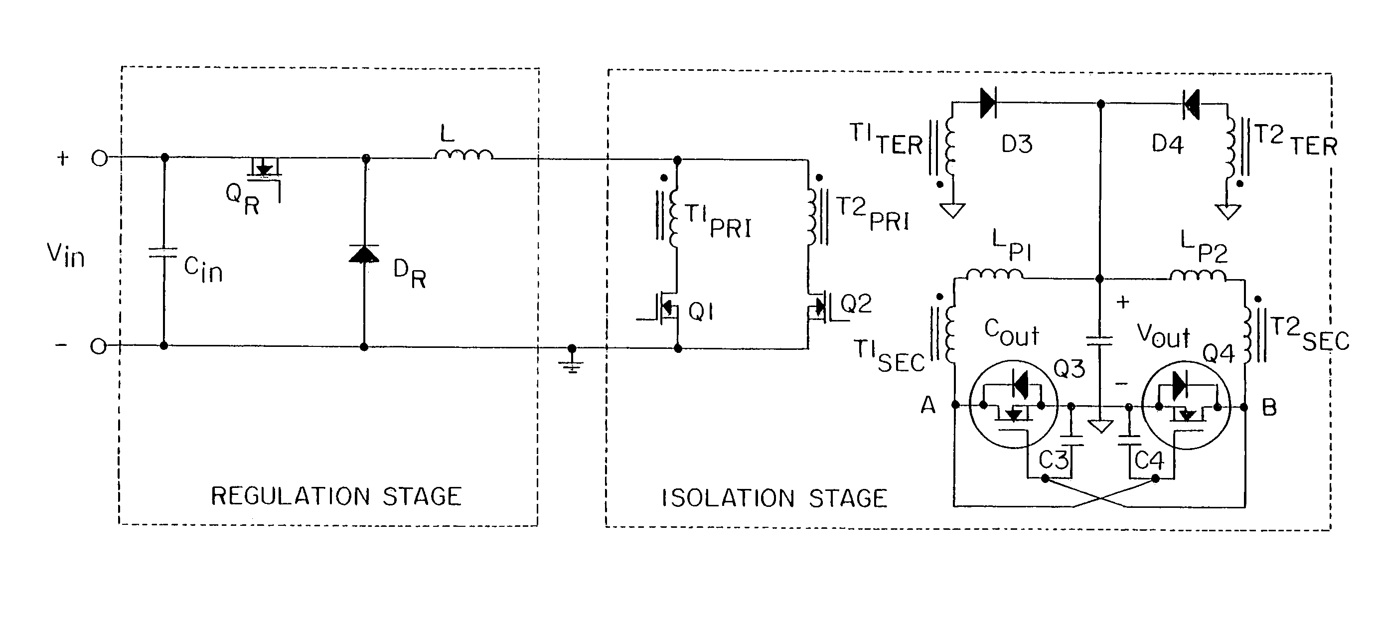
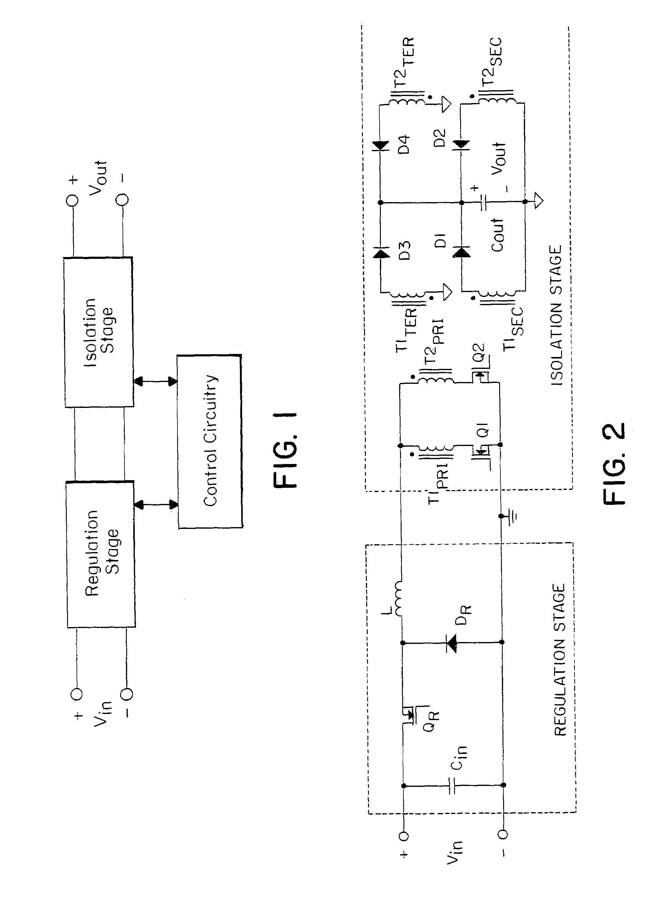
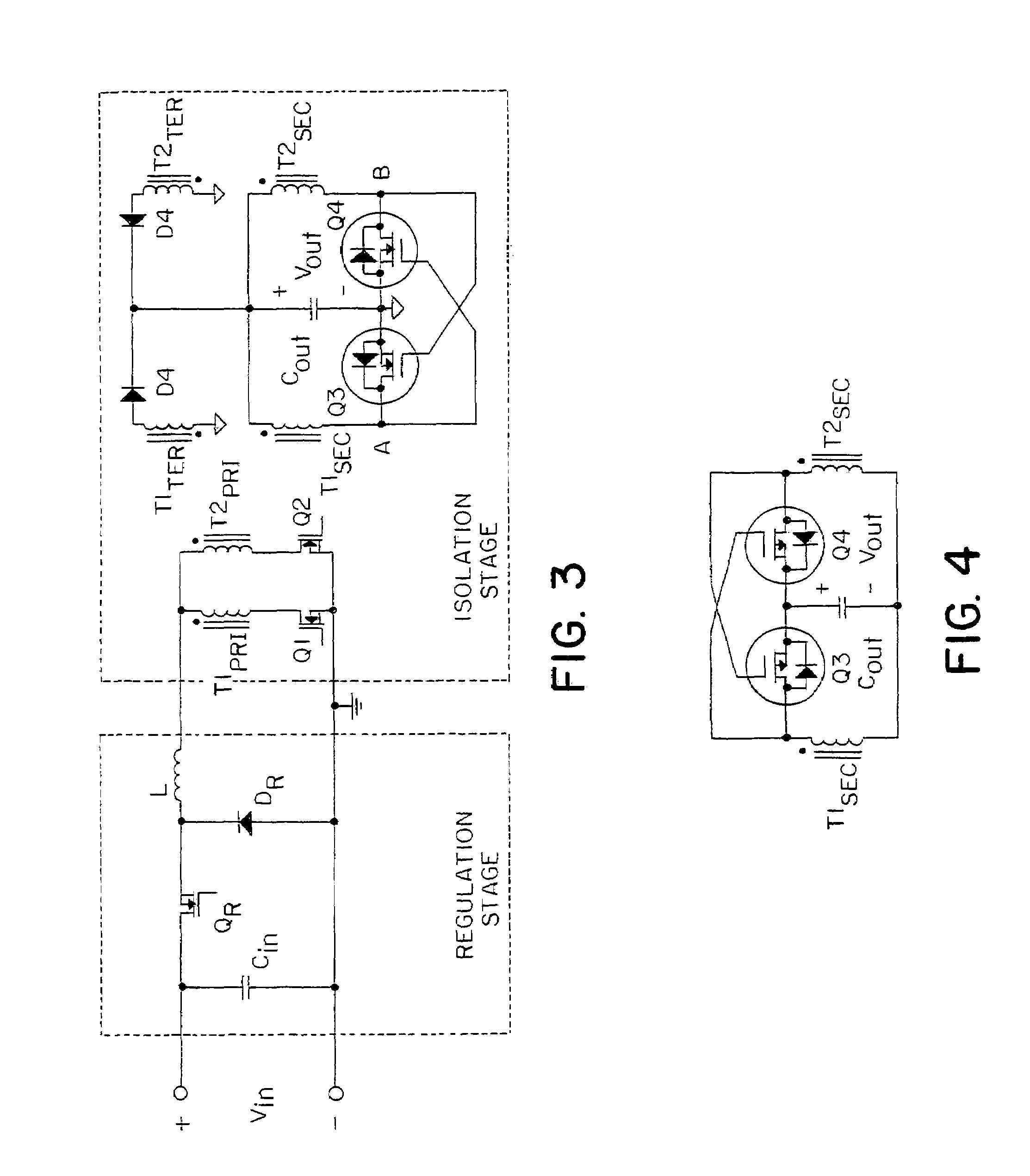
[0033]One embodiment of the invention described herein pertains to an electrically isolated DC-DC converter that might be used to deliver power at a low DC voltage (e.g. 5 volts) from a DC source such as a battery or a rectified utility. In such a converter a transformer is used to provide the electrical isolation and to provide a step-down (or step-up) in voltage level according to its turns-ratio. Switches in the form of power semiconductor transistors and diodes are used in conjunction with capacitors and inductors to create the conversion. A control circuit is typically included to provide the drive signals to the transistors' control terminals.
[0034]When the switching frequency is high (e.g. 100 kHz and above) it is typical today to use power MOSFETs and Schottky diodes for the converter's switches since these majority carrier devices can undergo faster switch transitions than minority carrier devices such as...
PUM
Abstract
A power converter nearly losslessly delivers energy and recovers energy from capacitors associated with controlled rectifiers in a secondary winding circuit, each controlled rectifier having a parallel uncontrolled rectifier. First and second primary switches in series with first and second primary windings, respectively, are turned on for a fixed duty cycle, each for approximately one half of the switching cycle. Switched transition times are short relative to the on-state and off-state times of the controlled rectifiers. The control inputs to the controlled rectifiers are cross-coupled from opposite secondary transformer windings.
Description
RELATED APPLICATIONS[0001]This application is a continuation of application Ser. No. 11 / 390,494, filed Mar. 27, 2006, which is a continuation of application Ser. No. 10 / 812,314, filed on Mar. 29, 2004, now U.S. Pat. No. 7,072,190, which is a continuation of application Ser. No. 10 / 359,457, filed Feb. 5, 2003, now U.S. Pat. No. 6,731,520, which is a continuation of application Ser. No. 09 / 821,655, filed Mar. 29, 2001, now U.S. Pat. No. 6,594,159, which is a divisional of application Ser. No. 09 / 417,867, filed Oct. 13, 1999, now U.S. Pat. No. 6,222,742, which is a divisional of Ser. No. 09 / 012,475, filed Jan. 23, 1998, now U.S. Pat. No. 5,999,417, which claims the benefit of U.S. Provisional Application 60 / 036,245 filed Jan. 24, 1997. The entire teachings of the above applications are incorporated herein by reference.BACKGROUND OF THE INVENTION[0002]This invention pertains to switching power converters. A specific example of a power converter is a DC-DC power supply that draws 100 wat...
Claims
Application Information
Patent Timeline
Application Date:The date an application was filed.
Publication Date:The date a patent or application was officially published.
First Publication Date:The earliest publication date of a patent with the same application number.
Issue Date:Publication date of the patent grant document.
PCT Entry Date:The Entry date of PCT National Phase.
Estimated Expiry Date:The statutory expiry date of a patent right according to the Patent Law, and it is the longest term of protection that the patent right can achieve without the termination of the patent right due to other reasons(Term extension factor has been taken into account ).
Invalid Date:Actual expiry date is based on effective date or publication date of legal transaction data of invalid patent.