Thermal airflow meter

a technology of airflow meter and airflow rate, which is applied in the direction of volume/mass flow measurement, measurement devices, instruments, etc., can solve the problems of airflow rate sensing error, complex molding process of airflow meter, and error in flow rate sensed flow rate, so as to enhance accuracy and enhance flow-rate measurement accuracy

Active Publication Date: 2007-09-18
HITACHI ASTEMO LTD
View PDF9 Cites 15 Cited by
  • Summary
  • Abstract
  • Description
  • Claims
  • Application Information

AI Technical Summary

Benefits of technology

[0011]An object of the invention is to enhance flow-rate measurement accuracy by resolving above-described problems in the conventional arts and to enhance accuracy with respect to an air temperature sensing.
[0015]Consequently, in spite of a structure in which the flow-rate measuring element is held by other constituent members, it becomes possible to correct for a flow rate sensing error due to heat-transfer from outside, and to sense a highly accurate airflow rate.
[0016]Further, because the first and second temperature sensors are provided on the first and second base members, respectively, so as to be separated from each other, a temperature difference between two points in the thermal airflow meter can be definitely taken out, thereby enabling to enhance accuracy in computation of an airflow rate. Further, by electrically connecting the first and second base members with each other, and by processing at least one of the airflow rate, an air temperature, an air passage wall face temperature, and so forth at the second base member, the signals from the temperature sensors, and so forth can be internally processed in the thermal airflow meter. Accordingly, there is no need for additionally installing output terminals of the temperature sensors, serving as connecting terminals of equipment outside the airflow meter. Furthermore, since a structure where the temperature sensors are embedded in a wall face of the airflow meter as in the conventional case is not adopted, the temperature sensors can be installed with greater ease.

Problems solved by technology

Such a change in ambient temperature and self-heating cause an error in a sensed flow rate of the airflow meter even if the temperature-compensating resistor is provided.
It is empirically known that if temperature of an air passage body through which air to be measured flows differs from a sensed air temperature, this will cause a airflow rate sensing error.
With such a configuration as described, however, the temperature-sensing resistor is embedded in resin, so that a molding process of the airflow meter becomes complex.

Method used


Image

  • Thermal airflow meter
  • Thermal airflow meter
  • Thermal airflow meter

Examples


Embodiment Construction

[0035]An embodiment of the invention is described hereinafter with reference to the accompanying drawings.

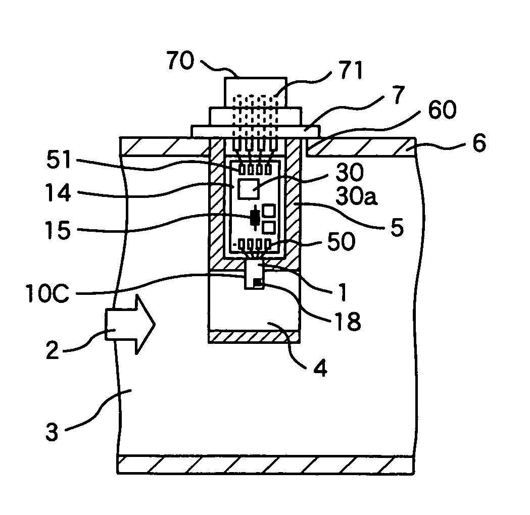
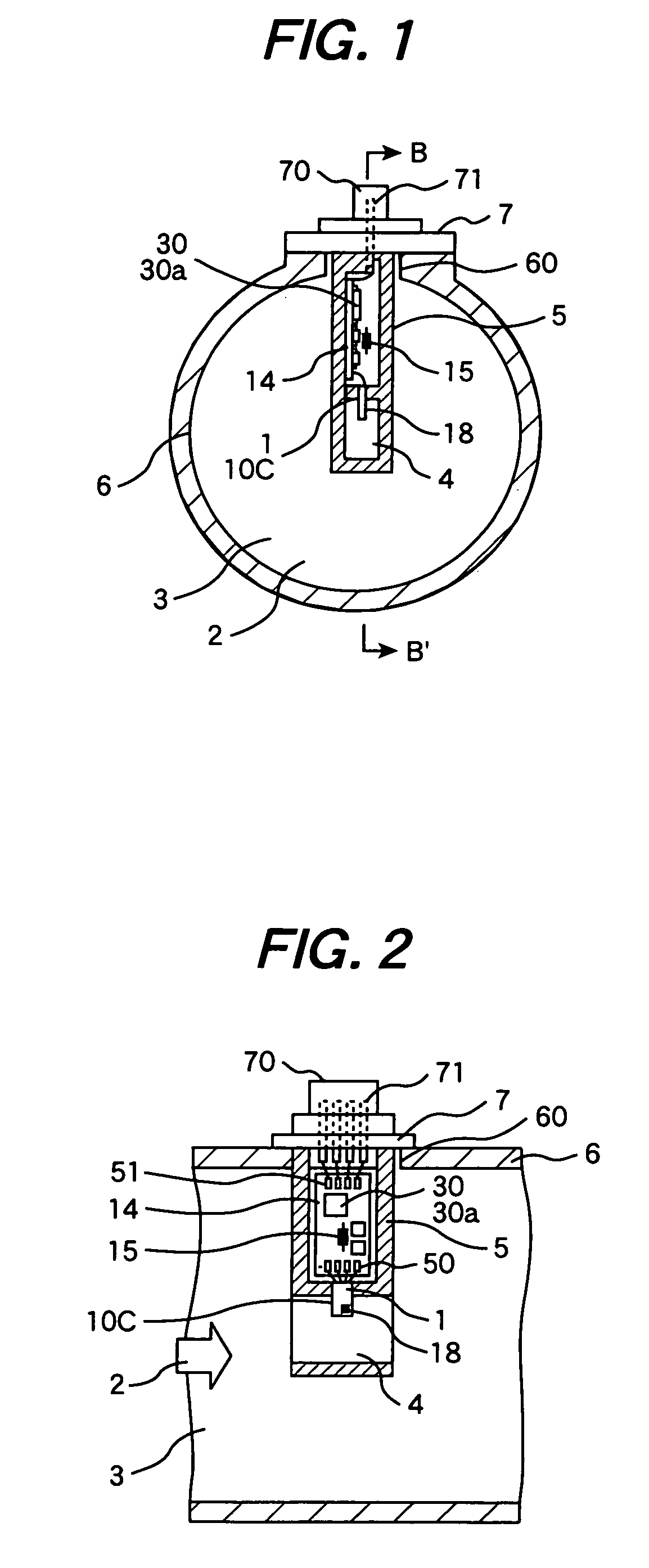
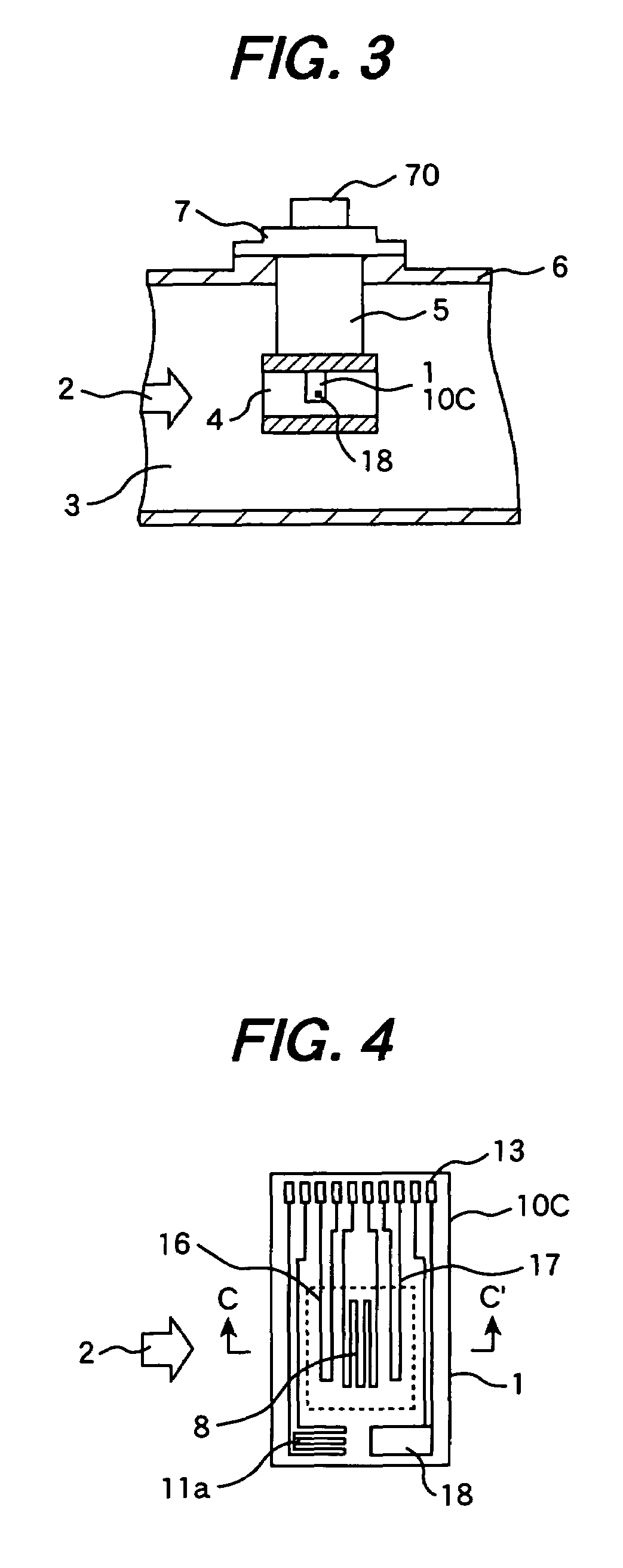
[0036]FIG. 1 is a cross-sectional view of one embodiment of a thermal airflow meter according to the invention, the cross-sectional view being perpendicular to the axis of an air passage thereof, FIG. 2 is a sectional view taken on line B-B′ of FIG. 1, and FIG. 3 a sectional view similar to FIG. 2, showing an outward appearance of a casing of the thermal airflow meter. FIG. 4 is a plan view of a flow-rate measuring element (hereinafter referred to merely as a measuring element) 1, and FIG. 5 a sectional view taken on line C-C′ of FIG. 4.

[0037]In FIGS. 1 to 3, the airflow meter comprises the measuring element 1, a secondary passage (a measurement passage) 4 where the measuring element 1 is disposed, a circuit board (second base member) 14, a casing 5 with the circuit board 14 housed therein, a holder 7 for supporting the casing 5, a connector 70, and so forth. The measuring eleme...


PUM


Abstract

A thermal airflow meter excellent in flow-rate measurement accuracy is provided. The airflow meter has a flow-rate measuring element comprising a heat resistor and a temperature-compensating resistor which are formed on the a first base member. A second base member of the airflow meter, provided with a drive circuit and a signal processor, is housed in a casing holding the flow-rate measuring element. The flow-rate measuring element is disposed in an air passage. Of two temperature sensors for measuring temperature at each of two points in the thermal airflow meter, respectively, a first temperature sensor is provided on the fist substrate of the flow-rate measuring element, and a second temperature sensor is provided inside the casing. The signal processor has a function of computing an airflow rate, an air temperature, and an air passage wall face temperature on the basis of an output signal of the flow-rate measuring element and respective output signals of the first and second sensors.

Description

TECHNICAL FIELD[0001]The present invention relates to a thermal airflow meter for measuring an airflow rate, and more particularly, to an airflow meter suitable for measuring an intake airflow rate of an internal combustion engine.BACKGROUND ART[0002]As a device for measuring an intake airflow rate in an internal combustion engine, a system, in which a heat resistor with temperature-dependence and a resistor (temperature-compensating resistor) for temperature-compensation of the heat resistor are disposed in an intake air passage (air passage) to measure the intake airflow rate, is well known.[0003]With this type of an airflow meter, even if heat of the heat resistor is released into airflow, a heating current flowing into the heat resistor is controlled so that a temperature difference between the heat resistor and the temperature-compensating resistor becomes constant, and a change in the current is directly or indirectly sensed, thereby measuring an airflow rate.[0004]In the case...

Claims


Application Information

Patent Timeline
Patent Type & Authority Patents(United States)
IPC IPC(8): G01F1/68G01F15/04G01F1/684G01F1/696G01F1/698
CPCG01F1/6842G01F1/696G01F1/6965
Inventor NAKANO, HIROSHIYAMADA, MASAMICHIMATSUMOTO, MASAHIROWATANABE, IZUMIHANZAWA, KEIJI
Owner HITACHI ASTEMO LTD
Why Eureka
Try Eureka