Plasma channel drilling process

a technology of plasma channel and drilling process, which is applied in the direction of plasma welding apparatus, surface mining, manufacturing tools, etc., can solve the problems of material fracture and fragmentation, and achieve the effect of improving the drilling ra

Active Publication Date: 2007-09-18
STRATHCLYDE UNIV OF
View PDF8 Cites 95 Cited by
  • Summary
  • Abstract
  • Description
  • Claims
  • Application Information

AI Technical Summary

Benefits of technology

[0025]For drilling in hard rock conditions it has been found that when the end face of the outer electrode is sharpened a better drilling rate is achieved in comparison with a non sharpened electrode. In test bore holes in samples of hard sandstone the sharpe

Problems solved by technology

This expansion of the discharge channel acts like a piston on the s

Method used


Image

  • Plasma channel drilling process
  • Plasma channel drilling process
  • Plasma channel drilling process

Examples


Embodiment Construction

[0042]Plasma-channel drilling, as explained herein, is the process of delivering electrical power to an electrode assembly acting as a drill bit, in a sequence of discrete high power pulses to form highly destructive short lived electrical plasma channel discharges, which in turn cause localised fragmentation and disintegration of a material, such as a rock structure, ahead of the electrode assembly.

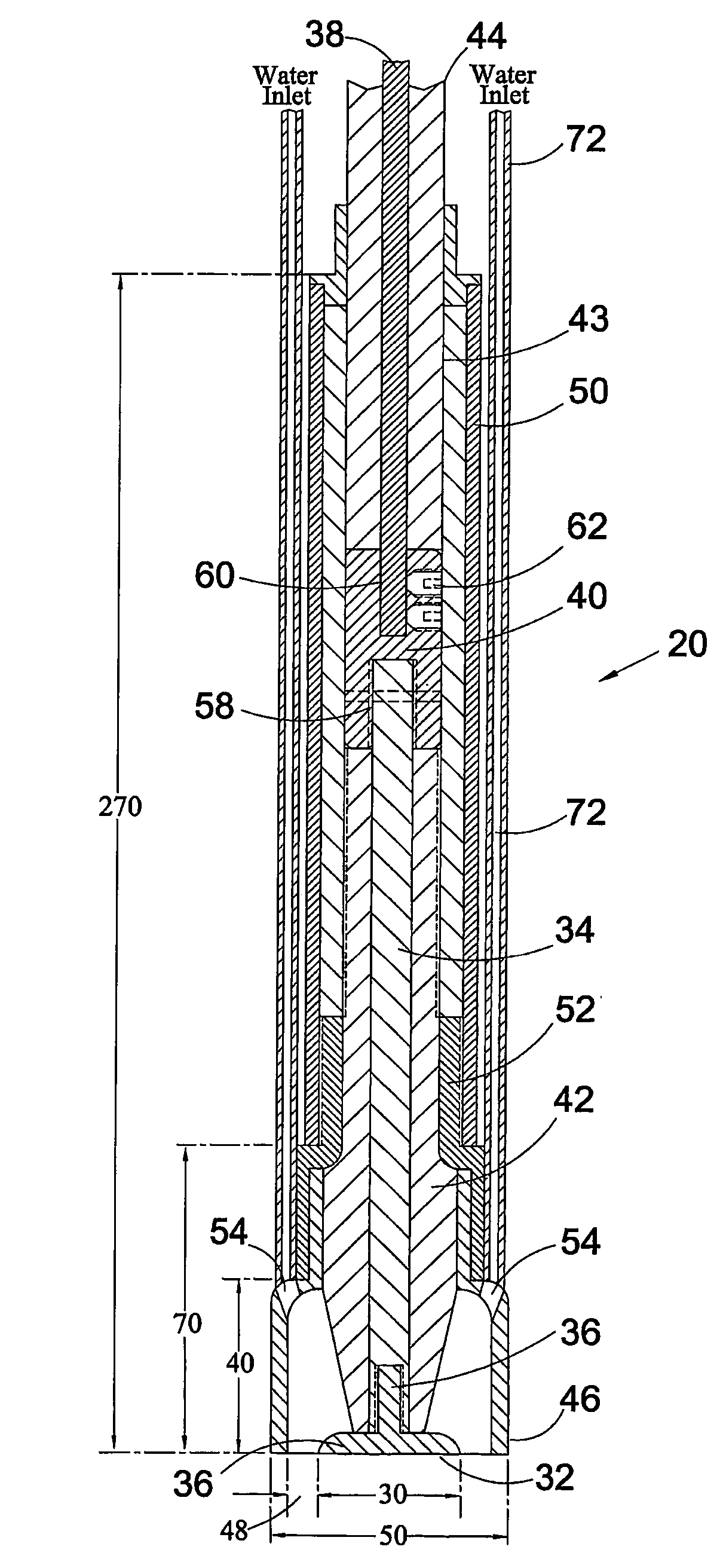
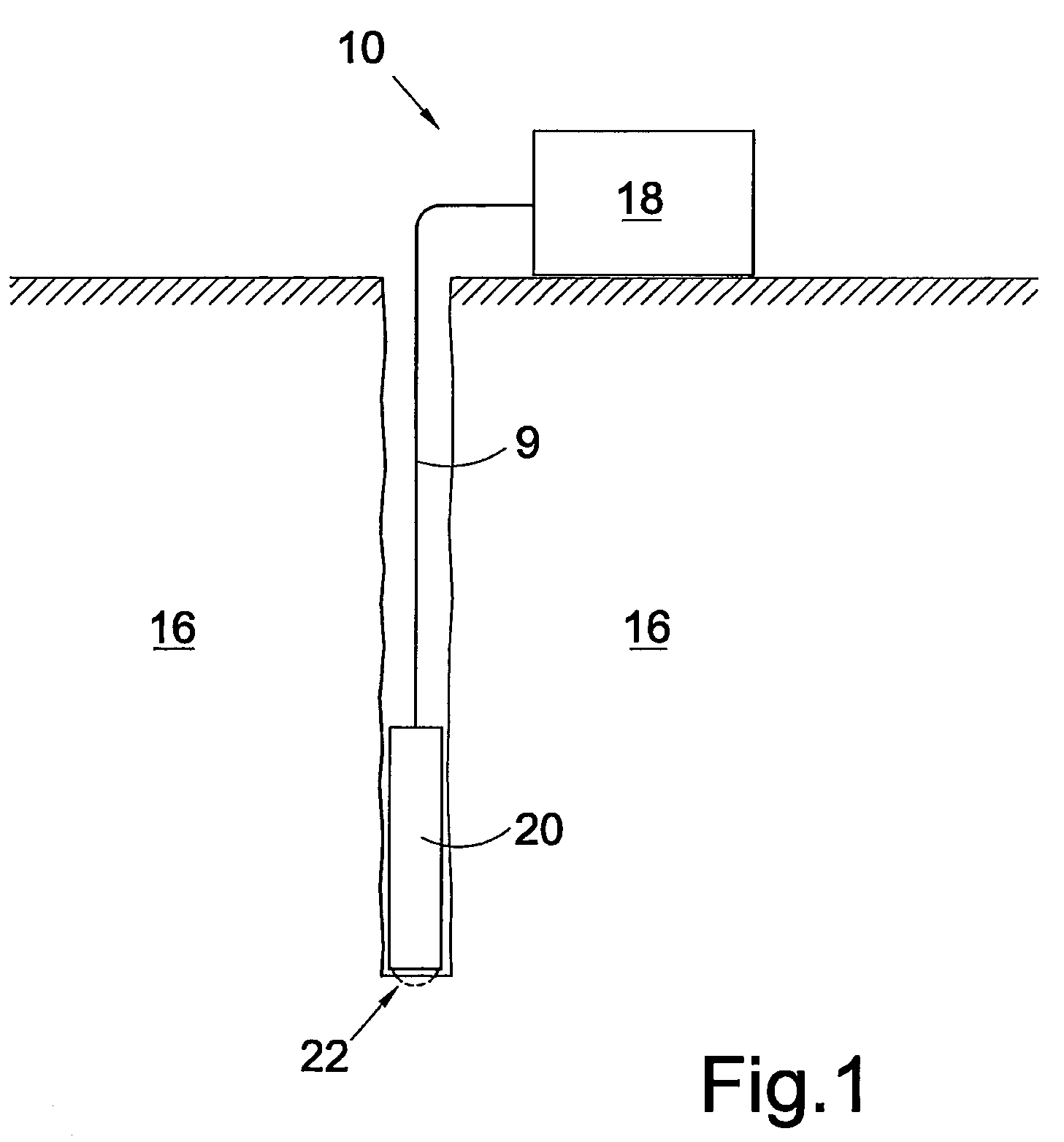
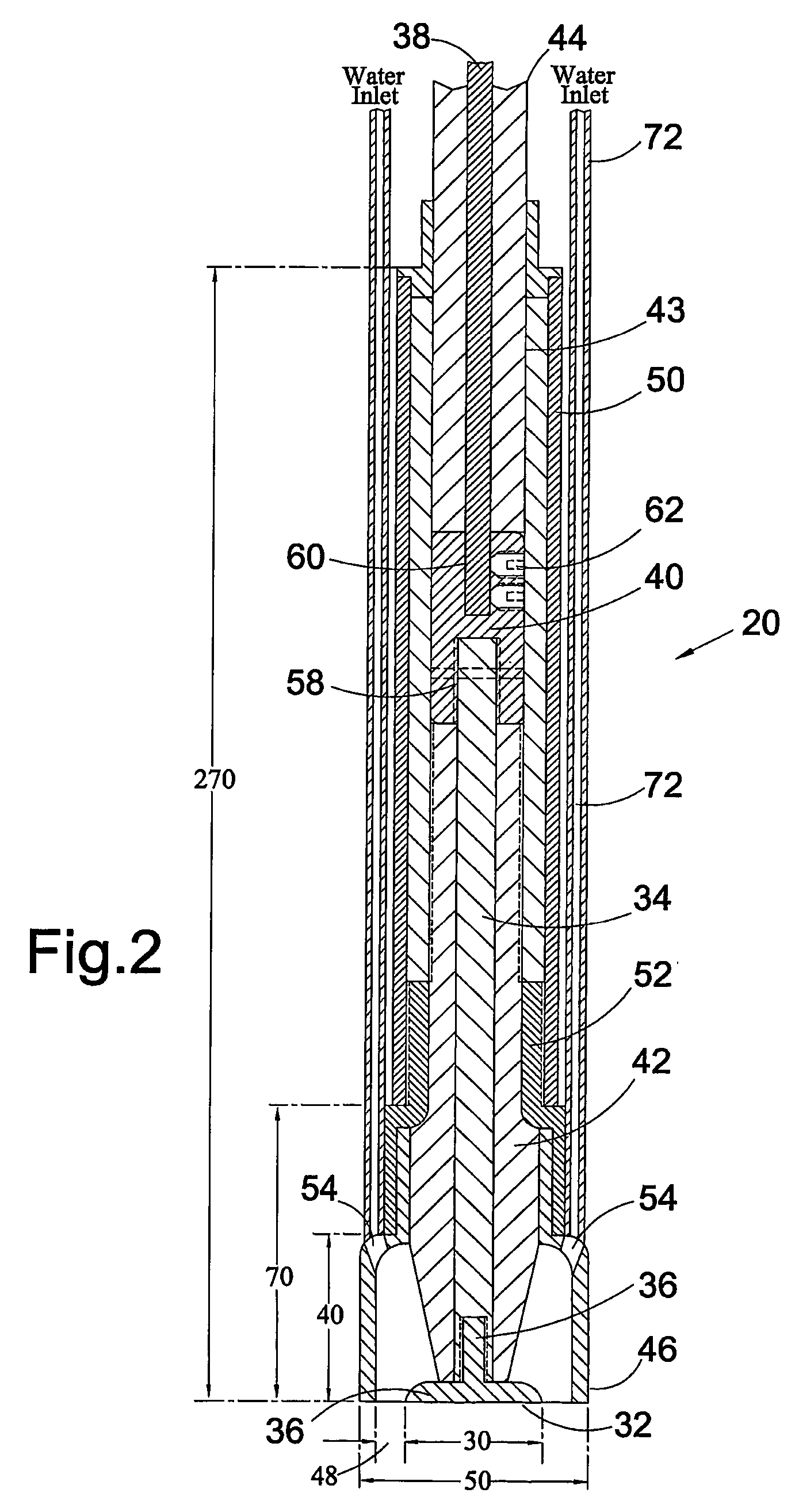
[0043]Referring to FIG. 1, there is illustrated a plasma-channel drilling apparatus, generally represented by reference numeral 10, for removal of surface material 12 from a body of material 16. The apparatus 10 comprises a high voltage pulsed generator 18 which is coupled by an HV cable 9 to an electrode assembly 20. The electrode assembly 20 is arranged such that a plasma channel 22 is produced within or on the surface of the body of material 16, which causes a localised region of the surface material 12 to fracture and fragment.

[0044]The high voltage pulsed generator 18 includes a dri...


PUM

PropertyMeasurementUnit
Timeaaaaaaaaaa
Timeaaaaaaaaaa
Timeaaaaaaaaaa

Abstract

Material is removed from a body of material, e.g. to create a bore hole, by plasma channel drilling. High voltage, high energy, rapid rise time electrical pulses are delivered many times per second to an electrode assembly in contact with the material body to generate therein elongate plasma channels which expand rapidly following electrical breakdown of the material causing the material to fracture and fragment.

Description

CROSS-REFERENCE TO RELATED APPLICATION[0001]This application is a Section 371 National Stage Application of International Application No. PCT / GB03 / 00622 filed on Feb. 12, 2003.BACKGROUND OF THE INVENTION[0002]1) Field of the Invention[0003]The present invention relates to a method and apparatus for removal of material from a body of material and, in particular but not exclusively, to a method and apparatus for removal of material to form a bore during drilling operations.[0004]2) Description of Related Art[0005]Currently known methods of plasma or electric arc drilling rely on the process of heating the material to be removed to its melting point. This process requires a significant amount of electrical power, and has the further difficulty of accurately focussing the power source on the material, or formation, which is to be removed. This may, therefore, result in the production of wide “kerfs” being formed during the process of producing a bore, as well as the waste of electrical ...

Claims


Application Information

Patent Timeline
IPC IPC(8): E21B7/15B23K10/00
CPCB23K10/00B23K10/006E21B7/15
Inventor MACGREGOR, SCOTT JOHNTURNBULL, STEVEN MCCALLUM
Owner STRATHCLYDE UNIV OF
Why Eureka
Try Eureka