
Distributed intelligence control for commercial refrigeration

a technology of commercial refrigeration and intelligence control, applied in the direction of refrigeration components, process and machine control, refrigeration safety arrangement, etc., can solve the problems of inability to provide information, substantial amount of wiring, substantial gaps in information concerning the operation of compressors, etc., and achieve the effect of simplifying wiring and facilitating assembly and installation

Inactive Publication Date: 2007-09-18
HUSNN
View PDF126 Cites 76 Cited by
  • Summary
  • Abstract
  • Description
  • Claims
  • Application Information

AI Technical Summary

Benefits of technology

[0017]Among the several objects and features of the present invention may be noted the provision of a commercial refrigeration system having distributed intelligence control functions; the provision of such a distributed intelligence control for a refrigeration system which can operate in case of main controller failure; the provision of such a refrigeration system control which is capable of continuously monitoring the status of operating parameters of multiplexed compressors; the provision of such a commercial refrigeration system control which provides substantial information about compressor operating characteristics; the provision of such a refrigeration system control which is easy to assemble and install; the provision of such a refrigeration system control which operates control functions at low voltage; and the provision of such a refrigeration system which has simplified wiring.
[0018]Further among the several objects and features of the present invention may be noted the provision of a compressor safety and control module for a commercial refrigeration system which is capable of communicating compressor status information; the provision of such a compressor safety and control module which is capable of monitoring its own compressor's operating parameters; the provision of such a compressor which shields sensors; the provision of such a compressor and compressor safety control module which provides highly accurate operating parameter data; the provision of such a compressor safety control module which can operate in cooperation with other compressor safety control modules if a master controller fails; the provision of such a compressor and compressor safety control module which is easy to wire into a refrigeration system.
[0019]Also among the objects and features of the present invention is the provision of a commercial refrigeration control system with increased system granularity. Such increase in granularity allows for closer matches of hardware to specific customer needs and requirements, with the need for little or no extemporaneous hardware. The provision of enhanced granularity also distributes the possibility of a failure over a wider hardware base, thereby limiting the severity of any potential adverse consequences to those functions contained within the failing device.

Problems solved by technology

Existing protection circuits are aware only that the operating limit has been traversed, and have no capability to provide information as to the actual value of the parameter.
Thus, a substantial amount of wiring is necessary to connect the compressor to the controller.
Even if the protection circuit is so wired for providing maximum information, there are substantial gaps in information concerning the operation of the compressor because of the absence of the ability to give an absolute reading of the parameter measured.
Thus, a number of shielded power lines are required for each compressor rack, making existing wiring complex and costly.
Thus, all of these items are exposed to potential damage during shipping and installation.
In prior art systems, however, a large amount of wiring is required to provide appropriate interfaces between the compressor rack and the various control valves, switches, and sensors in a given system.
The wiring is a complex task and the source of frequent system malfunction, particularly for newly installed refrigeration systems.

Method used


Image

  • Distributed intelligence control for commercial refrigeration
  • Distributed intelligence control for commercial refrigeration
  • Distributed intelligence control for commercial refrigeration

Examples


Embodiment Construction

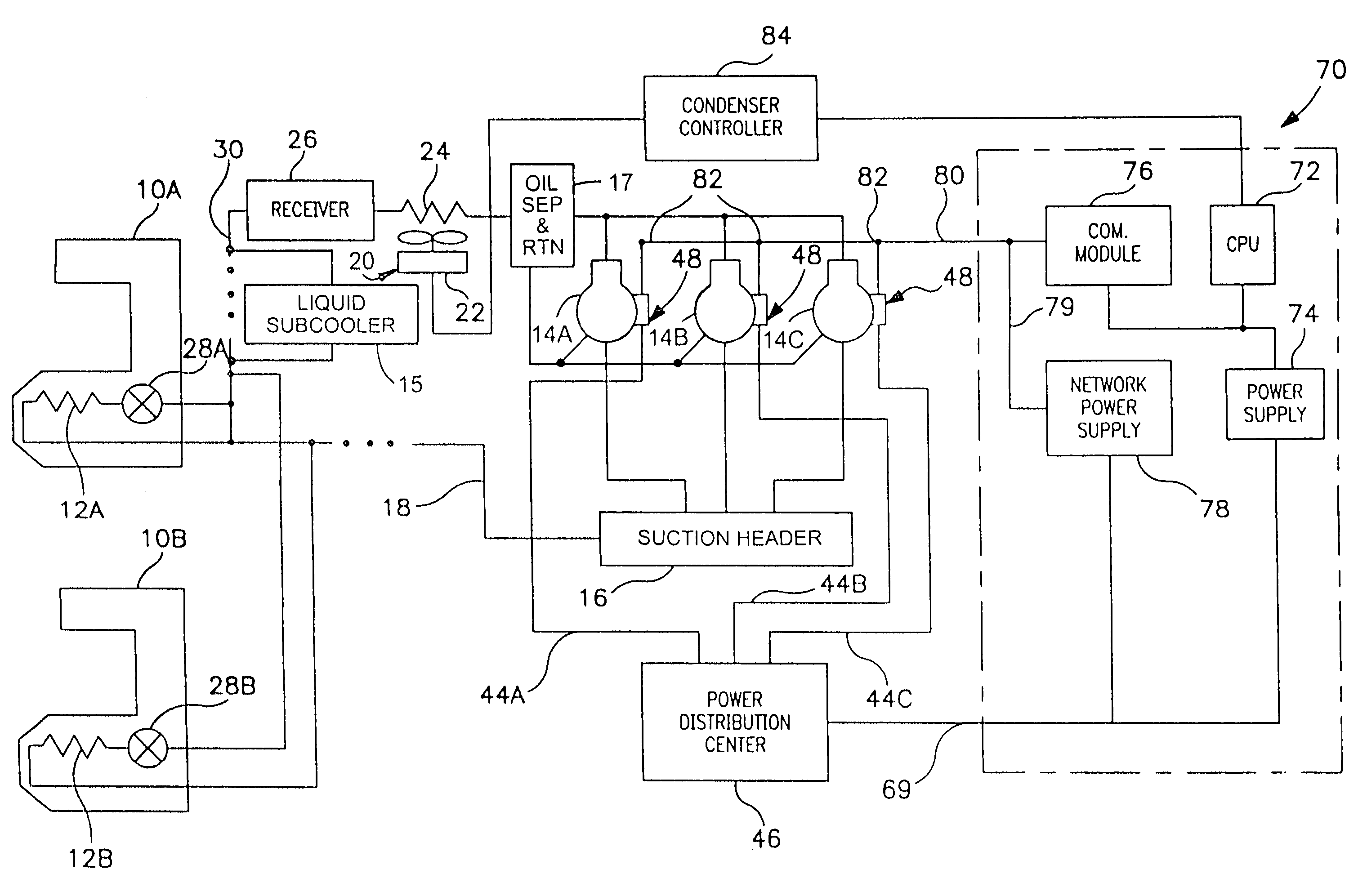
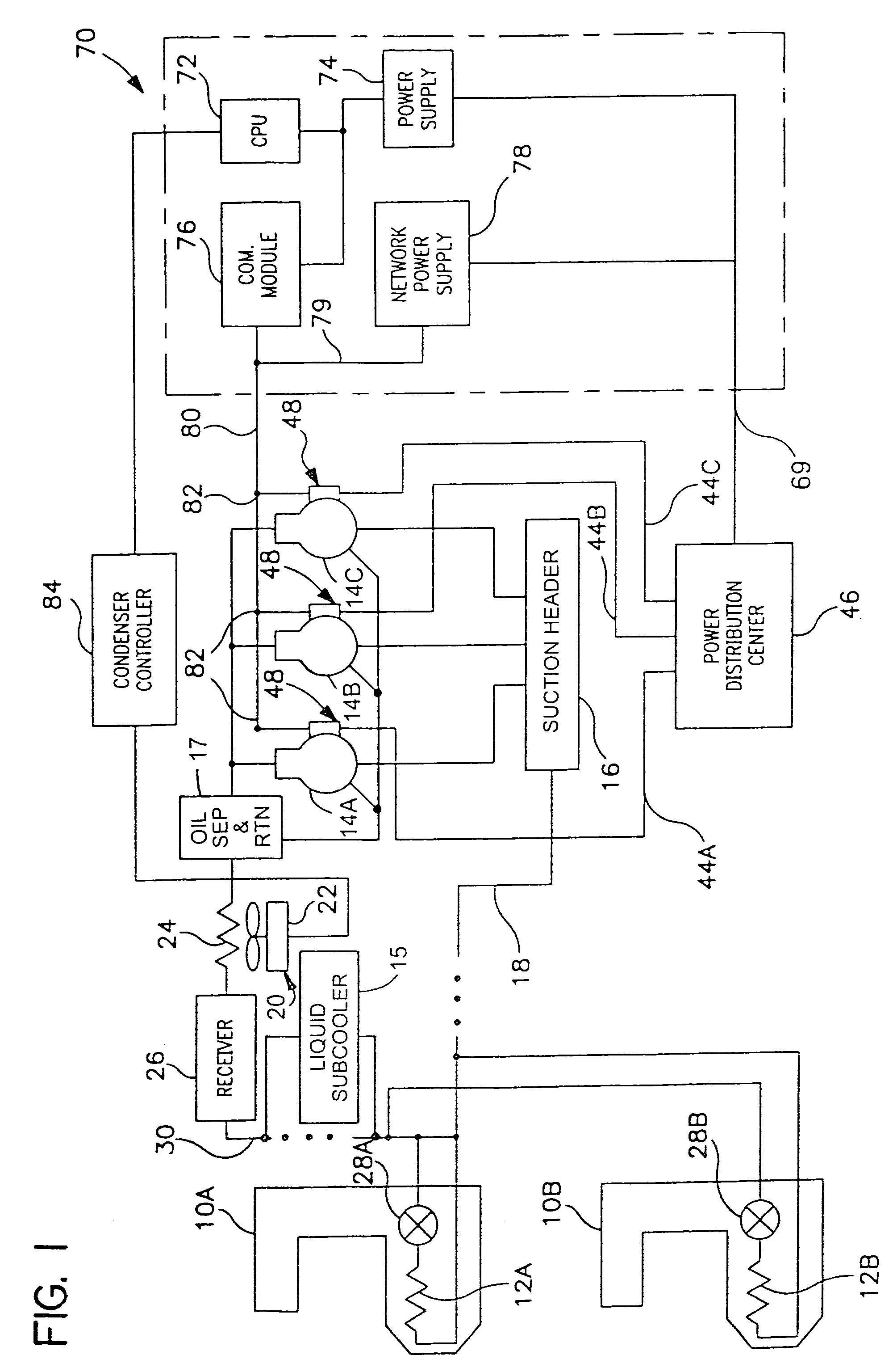
[0052]Referring now to FIG. 1, a commercial refrigeration system for use in a food store is shown to comprise one or more fixtures which are illustrated as food display merchandisers 10A, 10B in the shopping arena of a food store. The merchandisers 10A, 10B each incorporate at least one evaporator coil 12A, 12B (or like heat exchanger unit) disposed for cooling the merchandiser. Three multiplexed compressors (designated 14A, 14B, 14C, respectively) are connected by way of a suction header 16 and a low side return pipe 18 in fluid communication with the low side of the evaporators 12A, 12B for drawing refrigerant away from the evaporators. A condenser (generally indicated at 20) including a fan 22 and heat exchanger 24 is in fluid communication on the high discharge side of the compressors 14A, 14B, 14C for removing heat and condensing refrigerant pressurized by the compressors. Although an air-cooled condenser 20 is shown, other types of condensers, such as those liquid cooled from ...


PUM


Abstract

A commercial refrigeration system including a compressor, a condenser, a valve, and an evaporator coil, all of which are in fluid communication. The refrigeration system further including a fixture adapted to be cooled by the evaporator coil, a system controller operable to control operation of the refrigeration system, and a subsystem controller in communication with the system controller. The subsystem controller being operable to monitor at least one parameter of a subsystem having at least one of the compressor, condenser, valve, and fixture, and being further operable to execute a command from the system controller to affect the operation of the subsystem.

Description

CROSS REFERENCE TO RELATED APPLICATIONS[0001]This application is a continuation of U.S. patent application Ser. No. 09 / 849,900, filed May 4, 2001, entitled “DISTRIBUTED INTELLIGENCE CONTROL FOR COMMERCIAL REFRIGERATION”; which is a continuation-in-part of International Patent Application No. PCT / US01 / 08072, filed Mar. 14, 2001, entitled “DISTRIBUTED INTELLIGENCE CONTROL FOR COMMERCIAL REGRIGERATION”; which is a continuation-in-part of U.S. patent application Ser. No. 09 / 524,939, filed on Mar. 14, 2000, issued as U.S. Pat. No. 6,332,327; all of which are incorporated herein by reference.BACKGROUND OF THE INVENTION[0002]This invention relates generally to commercial refrigeration and more particularly to a commercial refrigeration system having unique power and communication wiring, as well as distribution of control intelligence features.[0003]Great advances have been made over the last 50 years in all aspects of refrigerated food store merchandisers and coolers and the various comme...

Claims


Application Information

Patent Timeline
IPC IPC(8): G05D23/00F25B49/00F25B5/00F25B7/00F25B5/02F25B6/04F25B25/00F25B41/04F25B49/02G05D23/19
CPCF25B49/02F25B49/022G05D23/19G05D23/1917F25B5/02F25B6/04F25B25/005F25B41/043F25B2400/075F25B2400/22F25B2500/06F25B2600/07F25B2600/111F25B2700/03F25B2700/1931F25B2700/1933F25B2700/21151F25B2700/21152F25B2700/21157Y02B30/743Y02B30/70F25B41/22
Inventor STREET, NORMAN E.SUNDERLAND, TED W.THOMAS, CHARLES D.SHAPIRO, DOROND'ANNA, MICHAEL J.DOERR, DENNIS
Owner HUSNN
Learn More