Separator with vane assembly and filter arrangement

a technology of separator and filter arrangement, which is applied in the direction of separation process, dispersed particle separation, chemistry apparatus and process, etc., can solve the problems of clogging the mesh with particulates and solids, and affecting the separation effect of liquid, so as to reduce the surface tension of liquid

Inactive Publication Date: 2007-09-18
HARBISON FISCHER
View PDF19 Cites 32 Cited by
  • Summary
  • Abstract
  • Description
  • Claims
  • Application Information

AI Technical Summary

Benefits of technology

[0020]In accordance with one aspect of the present invention, the step of directing the gas stream along a path further comprises flowing the liquid over a roughened surface on the sides of the path and reducing a surface tension of the liquid to cause a coalescing of the liquid.

Problems solved by technology

If the natural gas is transported through pipelines in a “wet” condition, the water acts to corrode the steel pipelines, causing possible ruptures and explosions.
These type of separators are expensive to manufacture.
The problem with using a wire mesh is that the mesh tends to become clogged with particulates and solids in the fluid stream.
When the mesh becomes clogged or partially blocked, the overall efficiency in the separator becomes reduced.
Compressors are particularly susceptible to contaminants in the fluid stream.
Another contaminant is salt that is produced by salt water wells.
The soap and salt contaminate compressors, necessitating frequent overhauls and other maintenance.
Such compressor maintenance results in down time and increased operating costs.

Method used


Image

  • Separator with vane assembly and filter arrangement
  • Separator with vane assembly and filter arrangement
  • Separator with vane assembly and filter arrangement

Examples


Embodiment Construction

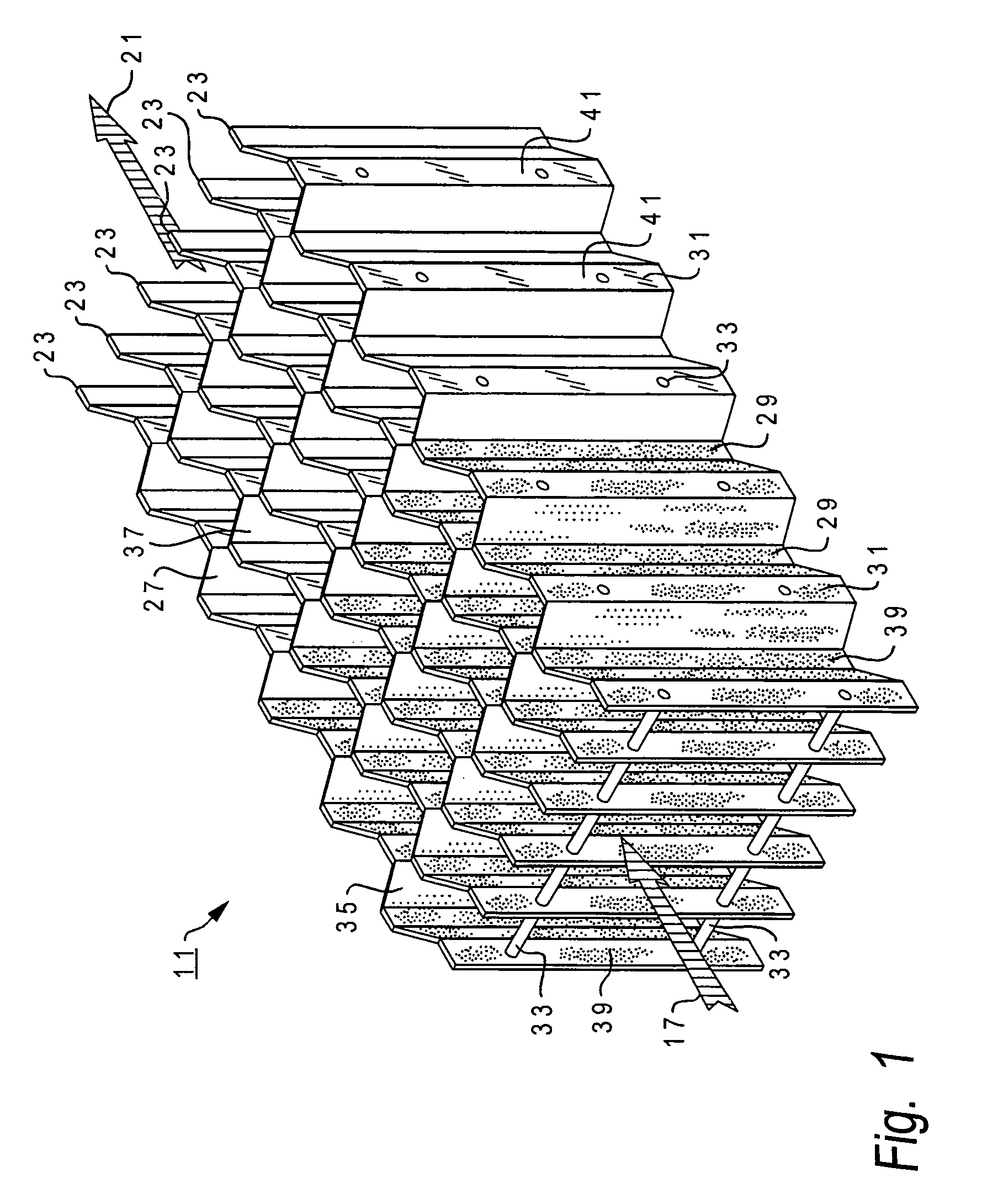
[0035]In FIG. 1, there is shown the vane assembly 11 in accordance with one embodiment. The vane assembly 11 is one component of a separator 13, such as is shown in FIG. 4. The vane assembly 11 is contained within a vessel 15 and fluid 17 is passed through the vane assembly. The fluid 17 contains gas and entrained liquid. The liquid 19 coalesces in the vane assembly 11, falling or draining down into the bottom of the separator vessel 15, while the gas 21 exits.

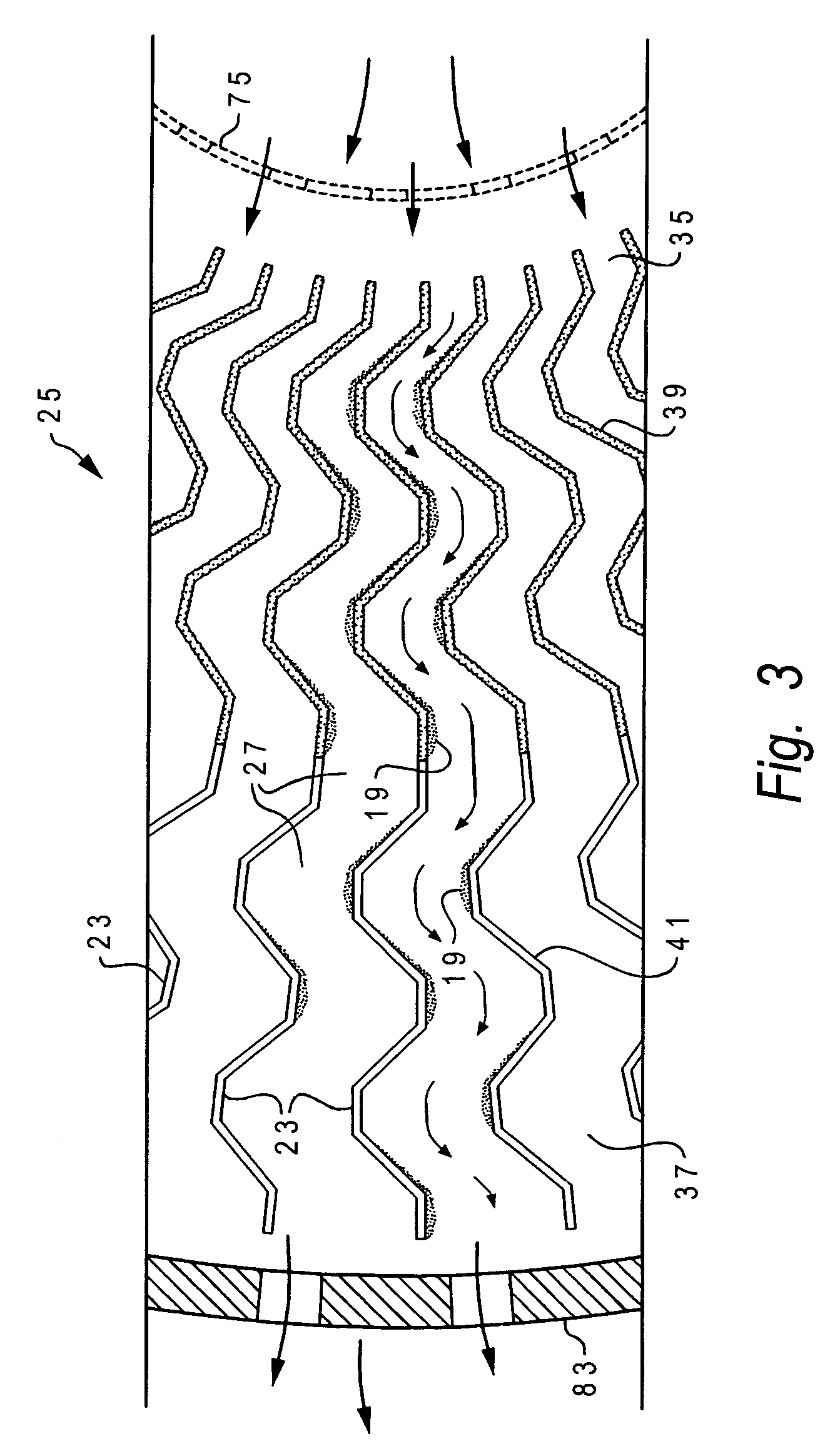
[0036]The vane assembly has a number of vanes 23 (see FIG. 1). With the vane assembly 11 of FIG. 1, the vanes 23 are generally parallel to one another. With the vane assembly 25 of FIG. 3, the vanes 23 extend in generally radial directions from a center.

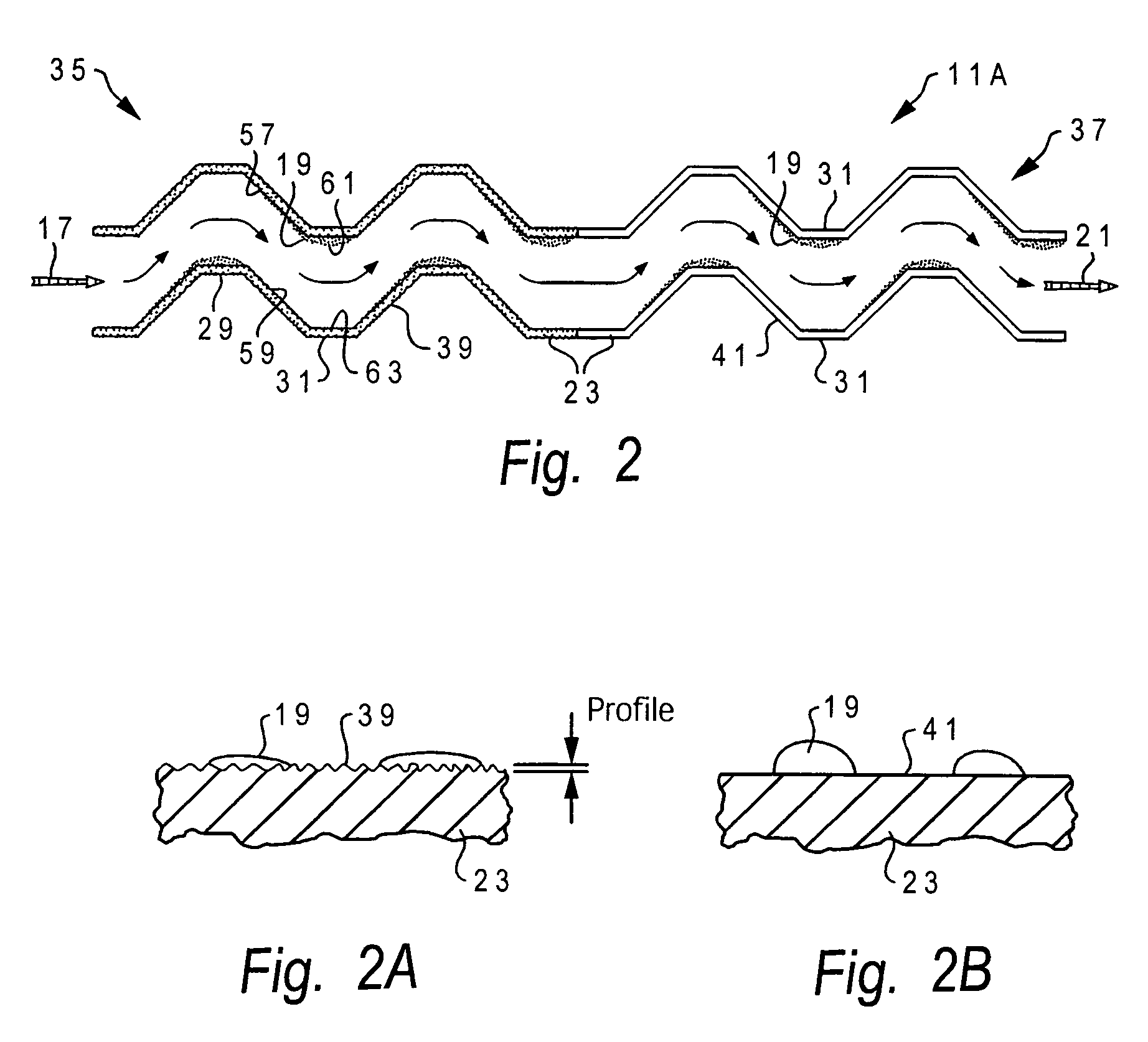
[0037]The vane assemblies 11, 25 provide serpentine paths 27 (see FIGS. 1-3) for the fluid to travel through. Such serpentine paths entice the liquid to separate from the gas. Serpentine type assemblies are shown in U.S. Pat. Nos. 3,813,855 and 5,112,375, the complete disclosur...


PUM

PropertyMeasurementUnit
roughnessaaaaaaaaaa
surface areaaaaaaaaaaa
wettableaaaaaaaaaa

Abstract

The separator has a vane assembly made up of a number of corrugated vanes that provide serpentine paths for the gas stream therethrough. As the gas stream flows through the serpentine paths, it changes direction and liquid in the gas stream impacts the surfaces of the vanes. The upstream section of the vane assembly has roughened surfaces to decrease the surface tension of the liquid, thereby causing the liquid to coalesce. The downstream section of the vane assembly has smooth surfaces so as to increase the surface tension of the liquid. The vane assembly is followed by filters, which capture the liquid that passes through the vane assembly. The vane assembly coalesces the liquid to enable the filters to operate more effectively.

Description

[0001]This application is a continuation-in-part of U.S. application Ser. No. 10 / 242,117, filed Sep. 12, 2002 now U.S. Pat. No. 6,757,926.FIELD OF THE INVENTION[0002]The present invention relates to apparatuses and methods for separating liquid from gas.BACKGROUND OF THE INVENTION[0003]Separators for separating liquid from gas are well known in the art. Separators are used, for example, to dry natural gas. The gas has liquid, such as water, entrained therein. If the natural gas is transported through pipelines in a “wet” condition, the water acts to corrode the steel pipelines, causing possible ruptures and explosions. Thus, it is desirable to economically and effectively remove the water from natural gas, and in general, to remove various types of liquids from various types of gasses.[0004]One prior art type of separator is taught by Hill et al., U.S. Pat. No. 3,813,855. The Hill patent teaches shaped vanes for channeling a fluid flow in a serpentine path. This path creates impact ...

Claims


Application Information

Patent Timeline
Patent Type & Authority Patents(United States)
IPC IPC(8): B01D45/00B01D45/08
CPCB01D45/08
Inventor SINDEL, ALLEN W.
Owner HARBISON FISCHER
Why Eureka
Try Eureka