Filter element, and filter device, duplexer, and high-frequency circuit each including said filter element

a filter element and filter device technology, applied in the field of duplexers and high-frequency circuits, can solve the problems of inherently low power durability, currently available ladder filters that do not exhibit power durability that is high enough for practical use, and reduce yield. yield, prevent the effect of increasing the size of the devi

Active Publication Date: 2007-09-18
TAIYO YUDEN KK
View PDF22 Cites 25 Cited by
  • Summary
  • Abstract
  • Description
  • Claims
  • Application Information

AI Technical Summary

Benefits of technology

[0016]A more specific object of the present invention is to provide a filter element that has single-terminal piezoelectric thin-film resonators arranged in series arms and parallel arms, prevents increase of device size, enhances power durability, and prevents yield decrease.

Problems solved by technology

SAW filters, however, have a drawback in inherently having low power durability, since minute comb-like electrode patterns are used in those SAW filters.
Although improvements such as the above have been made to obtain higher power durability, currently available ladder filters do not exhibit power durability that is high enough for practical use.
When two or more resonators connected-in series are employed instead of a single series-arm resonator, however, the number of resonators increases accordingly, and the area of the divided resonators is larger than the area of the single series-arm resonator, resulting in a larger necessary total area.
In such a case, the total necessary area of the resonators becomes very large, and hinders decrease of the device size.
In a case of a membrane-type piezoelectric thin-film resonator in which a cavity for acoustic insulation from the substrate is formed under each resonator, the piezoelectric thin-film resonator breaks easily as the area of the resonators becomes larger, resulting in a difficult problem of having a poorer yield.

Method used


Image

  • Filter element, and filter device, duplexer, and high-frequency circuit each including said filter element
  • Filter element, and filter device, duplexer, and high-frequency circuit each including said filter element
  • Filter element, and filter device, duplexer, and high-frequency circuit each including said filter element

Examples


first embodiment

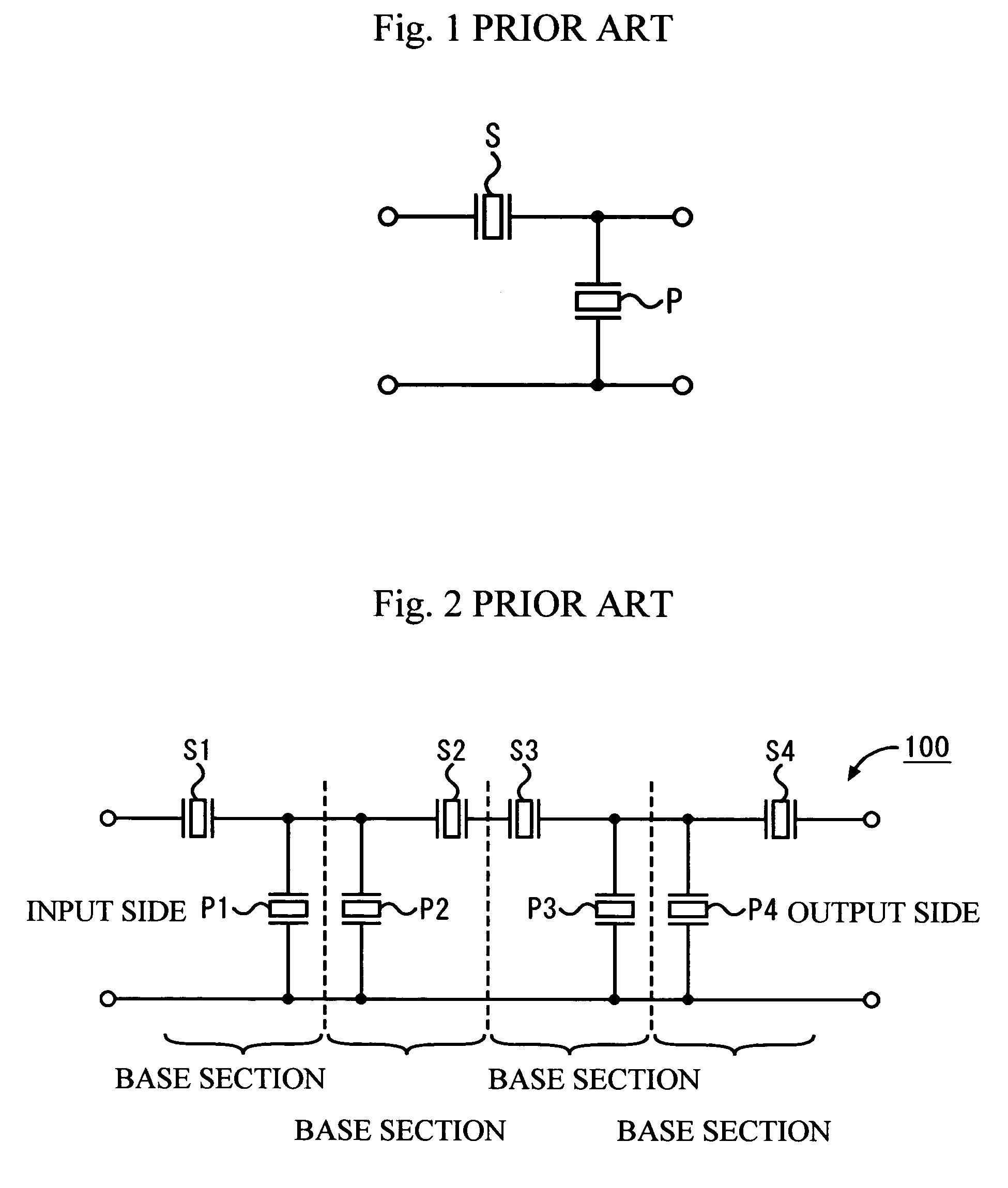
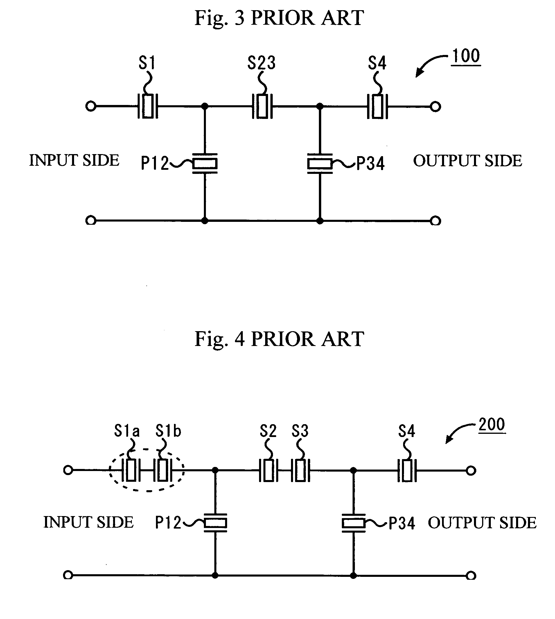
[0052]A first embodiment of the present invention will now be described in detail. FIG. 7 shows an equivalent circuit of a ladder filter 400 having only single-terminal pair piezoelectric thin-film resonators (hereinafter referred to simply as “resonators”) as a comparative example. FIG. 8 is a plan view illustrating the filter structure of the ladder filter 400. In this comparative example, there are four stages of ladder-type circuit base sections, and the two parallel resonators in the middle are combined into one in the same manner as in the conventional example shown in FIG. 3.

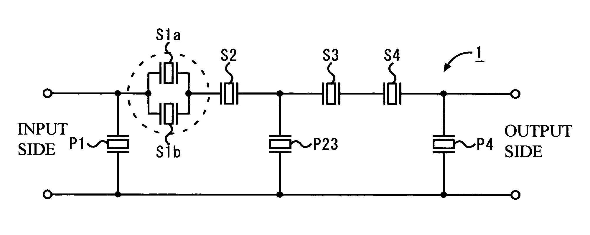
[0053]As the first embodiment of the present invention as opposed to the comparative example, FIG. 9 shows an equivalent circuit of a ladder filter 1 in which only the first-stage series-arm resonator on the signal input side is divided into two resonators connected in parallel. FIG. 10 is a plan view illustrating the filter device of the ladder filter 1. FIG. 11A is a section view of the filter structure...

second embodiment

[0063]Another example structure of the ladder filter 1 of the first embodiment will now be described below, with reference to the accompanying drawings.

[0064]FIG. 15 shows an equivalent circuit of a ladder filter 2 in which every series-arm resonator is divided into two resonators connected in parallel. In this filter, the divided series-arm resonators (S1a, S1b, S2a, S2b, S3a, S3b, S4a, and S4b) are uniform in size, each having an area of 54 μmφ, which is approximately half as large as the area (77 μmφ) of each of the single series-arm resonators S1 through S4 of the comparative example. The other aspects of this structure are the same as those of the first embodiment, and therefore, explanation of them is omitted herein.

[0065]FIG. 16 shows an equivalent circuit of a ladder filter 3 in which each of the first-stage and second-stage series-arm resonators on the signal input side is divided into three resonators connected in parallel, and each of the third-stage and fourth-stage seri...

third embodiment

[0070]In the following, a lattice filter using single-terminal pair film resonators will be described as a third embodiment of the present invention, with reference to the accompanying drawings. In this lattice filter, two or more resonators, instead of a single resonator, are connected in parallel.

[0071]FIG. 19 shows an equivalent circuit of a lattice filter 500 as a comparative example. As shown in FIG. 19, the lattice filter 500 has two series arms and two parallel arms. In FIG. 19, the resonators arranged in the series arms (the series-arm resonators) are denoted by S1 and S2, and the resonators arranged in the parallel arms (the parallel-arm resonators) are denoted by P1 and P2.

[0072]FIG. 20 illustrates a lattice filter 6 in accordance with this embodiment. In this lattice filter 6, each of the series-arm resonators S1 and S2 of the lattice filter 500 is divided into three resonators connected in parallel, and each of the parallel-arm resonators P1 and P2 of the lattice filter ...


PUM


Abstract

A filter element includes resonators that are arranged in series arms and parallel arms in a circuit. In this filter element, at least one of the series-arm resonators includes a plurality of single-terminal pair piezoelectric thin-film resonators connected in parallel.

Description

BACKGROUND OF THE INVENTION[0001]1. Field of the Invention[0002]The present invention generally relates to a filter element having a piezoelectric thin-film resonator and a filter device including the filter element, and more particularly, to a duplexer and a high-frequency circuit that are required to have high power durability to be used at the front end of a radio terminal.[0003]2. Description of the Related Art[0004]In recent years, wireless terminals such as portable telephones have been rapidly becoming smaller and lighter. In this trend, components for those terminals are expected to become smaller and exhibit higher performance. In duplexers to be used at the front ends of RF circuits, for example, conventional dielectric filters are being replaced with surface acoustic wave (SAW) filters that are much smaller than the conventional dielectric filters.[0005]SAW filters, however, have a drawback in inherently having low power durability, since minute comb-like electrode patter...

Claims


Application Information

Patent Timeline
Patent Type & Authority Patents(United States)
IPC IPC(8): H03H9/70H03H9/54H03H9/00H03H9/10H03H9/17H03H9/56H03H9/58H03H9/74H04B1/3822H04B1/40
CPCH03H9/0095H03H9/1014H03H9/564H03H9/568H03H9/17
Inventor NISHIHARA, TOKIHIROYOKOYAMA, TSUYOSHISAKASHITA, TAKESHIMIYASHITA, TSUTOMU
Owner TAIYO YUDEN KK
Why Eureka
Try Eureka