
Liquid crystal display device, method for controlling the same, and portable terminal

a liquid crystal display device and display device technology, applied in the direction of instruments, computing, electric digital data processing, etc., can solve the problems of method inability to cope and residual image forming distortion on the screen, and achieve the effect of preventing the formation of residual image caused by residual charge in the pixels

Inactive Publication Date: 2007-09-18
JAPAN DISPLAY WEST
View PDF3 Cites 70 Cited by
  • Summary
  • Abstract
  • Description
  • Claims
  • Application Information

AI Technical Summary

Benefits of technology

[0007]The present invention is made in view of the above problem, and it is an object of the present invention to provide a liquid crystal display device in which, by eliminating a residual image caused by residual electric charge in pixels even if a power-off state suddenly occurs, it is ensured that screen distortions in the power-off state can be prevented, a method for controlling the liquid crystal display device, and a portable terminal in which the liquid crystal display device is used as a screen display panel.
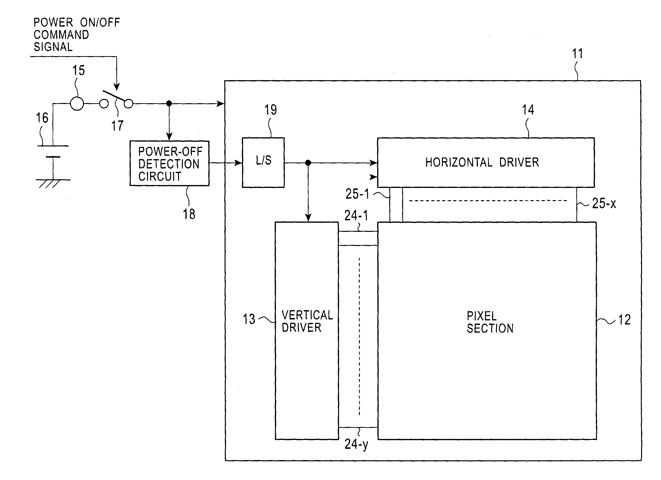
[0014]According to the present invention, when a liquid crystal display device is in a power-off state, by switching on all the pixels of a pixel section of the liquid crystal display device, and setting all signal lines to each have a potential equal to the potential of common electrodes in all the pixels, a discharging path for discharging residual charge in all the pixels is formed, and the discharging path can instantaneously discharge the residual charges in all the pixels. Therefore, even if a power-off state suddenly occurs, it is ensured that screen distortions formed by a residual image caused by the residual charge in the pixels can be prevented.

Problems solved by technology

When a liquid crystal display device is switched off (in a power-off state), residual electric charge in pixels may cause a residual image forming distortions on the screen.
Thus, this method cannot cope with a sudden occurrence of the power-off state, which is an instantaneous event.

Method used


Image

  • Liquid crystal display device, method for controlling the same, and portable terminal
  • Liquid crystal display device, method for controlling the same, and portable terminal
  • Liquid crystal display device, method for controlling the same, and portable terminal

Examples


first embodiment

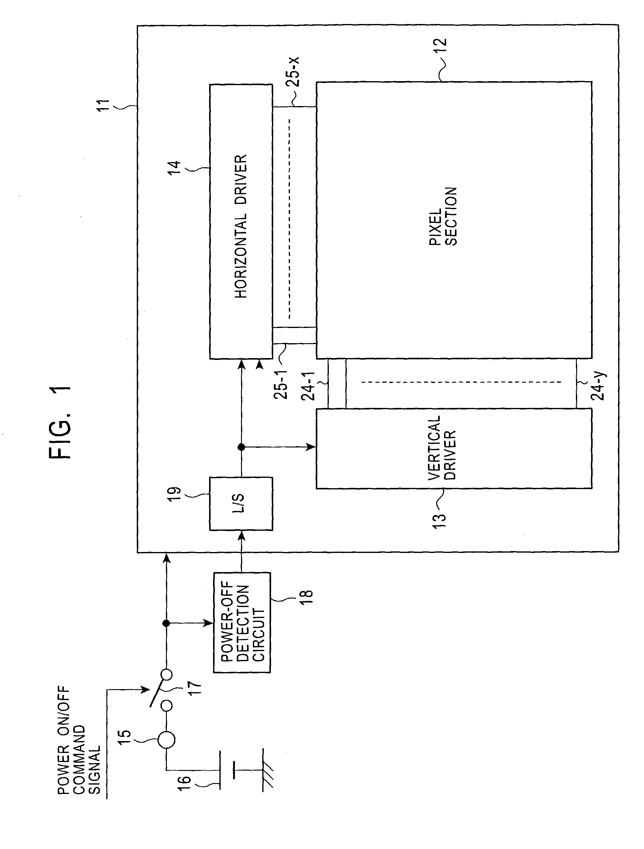
[0027]FIG. 1 is a block diagram showing a liquid crystal display device according to a first embodiment of the present invention. The liquid crystal display device according to the first embodiment operates on the condition that it uses a battery as a power supply.

[0028]In FIG. 1, pixels including active elements are arranged in a matrix on a transparent insulating substrate (e.g., a glass substrate 11) to form an active matrix pixel section (display section) 12.

[0029]The glass substrate 11 is disposed opposing another glass substrate, with a predetermined distance provided therebetween. Both glass substrates have liquid crystal material therebetween to constitute a liquid crystal display panel (LCD panel).

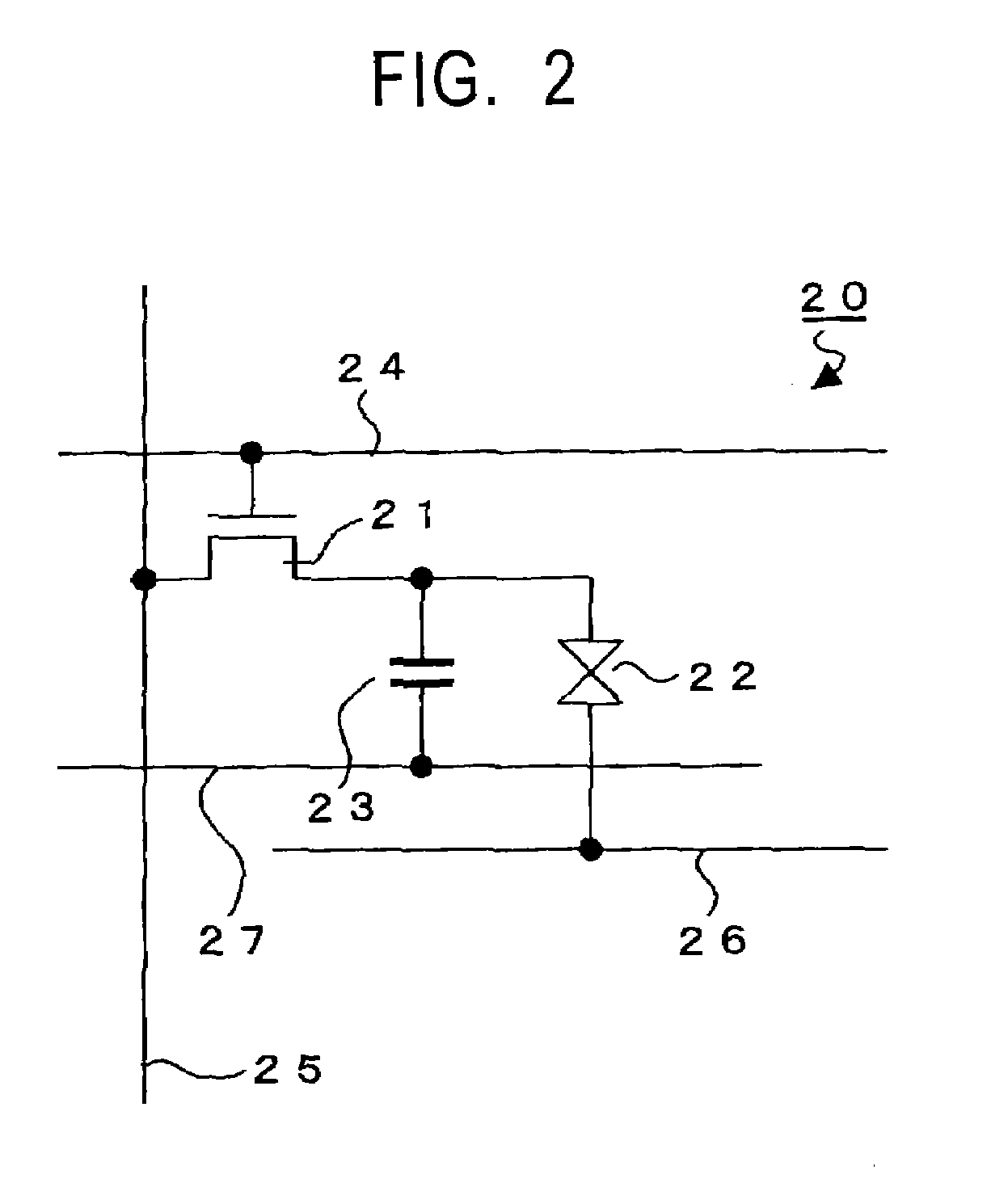
[0030]An example of each pixel 20 in the pixel section 12 is shown in FIG. 2. The pixel 20 includes a pixel transistor 21 as an active element (e.g., a thin film transistor (TFT)), a liquid crystal cell 22 having a pixel electrode connected to the drain electrode of the TFT 21, an...

second embodiment

[0054]FIG. 7 is a block diagram showing a liquid crystal display device according to a second embodiment of the present invention. In the second embodiment, the present invention is applied to a precharging active matrix liquid crystal display device. In FIG. 7, portions equivalent to those in FIG. 1 are denoted by identical reference numerals. The liquid crystal display device according to the second embodiment is also based on the condition that it uses a battery as a power supply.

[0055]The liquid crystal display device according to the second embodiment includes a precharging driver 60 for writing a precharging signal Psig before a horizontal driver 14 writes display signals in data lines 25-1 to 25-x, in addition to the components according to the first embodiment. Regarding the precharging signal Psig, for example, in a normally-white liquid crystal display device, a gray or black level is used as a signal level.

[0056]Operation and advantages obtained by precharging are describ...

third embodiment

[0068]FIG. 9 is a block diagram showing an active-matrix liquid crystal display device according to a third embodiment of the present invention. In FIG. 9, portions equivalent to those in FIG. 1 are denoted by identical reference numerals. The liquid crystal display device according to the third embodiment is based on the condition that it uses a battery 16 as a power supply.

[0069]The liquid crystal display device according to the second embodiment has a first power-off mode and a second power-off mode. In the first power-off mode, in the power-off state, white level signals are written in all the pixels in the pixel section 12 in the case of the normally white mode, and black level signals are written in all the pixels in the pixel section 12 in the normally black mode, with pixels in the pixel section 12 sequentially selected in units of rows. In the second power-off mode, in the power-off state, the active elements of all the pixels in the pixel section 12 are switched on and all...


PUM


Abstract

An active-matrix liquid crystal display device has pixels arranged in a matrix which each include a thin film transistor (TFT) as an active element. When the device is in a power-off state, TFTs in all the pixels are switched on, and all horizontal switches are turned on so that all data lines are supplied with a potential equal to the potential of common electrodes of the pixels. This forms a discharging path for discharging residual charge in all the pixels, and the discharging path can instantaneously discharge the residual charges.

Description

BACKGROUND OF THE INVENTION[0001]1. Field of the Invention[0002]The present invention relates to liquid crystal display devices, methods for controlling the devices, and portable terminals, and in particular, to an active-matrix liquid crystal display device including active elements for pixels, a method for controlling the liquid crystal display device when it is in a power-off state, and a portable terminal in which the liquid crystal display device is used as a screen display unit.[0003]2. Description of the Related Art[0004]When a liquid crystal display device is switched off (in a power-off state), residual electric charge in pixels may cause a residual image forming distortions on the screen.[0005]A method for shutting off the supply of power to a liquid crystal panel has been employed as a measure in the related art for preventing screen distortions occurring in the power-off state. In this method, in response to a power-off command issued when a user operates a power-on / off ...

Claims


Application Information

Patent Timeline
IPC IPC(8): G06F3/038G09G5/00G02F1/133G09G3/20G09G3/36
CPCG09G3/3648G09G3/3677G09G3/3688G09G2310/0248G09G2310/0245G09G3/36
Inventor TOYOZAWA, NOBORUNAKAJIMA, YOSHIHARUTOYOSHIMA, YOSHIHIKO
Owner JAPAN DISPLAY WEST
Learn More