Image input apparatus and method

a technology of image input and input apparatus, which is applied in the field of image input apparatus, can solve the problems of difficult operation by users, inconvenient use, and inferior image quality after 10 seconds of jpeg compression dedicated to still images, and achieve the effect of convenient us

Inactive Publication Date: 2007-09-18
CANON KK
View PDF18 Cites 4 Cited by
  • Summary
  • Abstract
  • Description
  • Claims
  • Application Information

AI Technical Summary

Benefits of technology

[0017]It is an object of the present invention to solve the above problems and provide an image input apparatus and method capable of making a user easy to use.
[0018]It is another object of the present invention to provide an image input apparatus and method capable of easily instructing a compression operation.

Problems solved by technology

There are the following problems of picking up still images.
This is inconvenient to use.
Furthermore, the image quality after 10 seconds is inferior to that of JPEG compression dedicated to still images.
This poses a problem of difficult operations by a user.
This problem becomes conspicuous, especially when the video camera is not mounted on the stand but is held with a hand.
It is very difficult to operate a mouse with a right hand while the video camera is held with the left hand.

Method used


Image

  • Image input apparatus and method
  • Image input apparatus and method
  • Image input apparatus and method

Examples


first embodiment

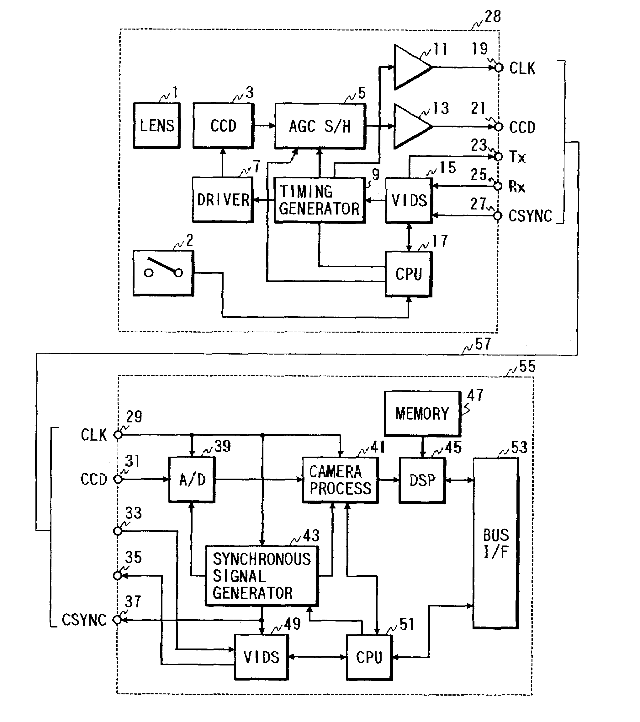
[0035]FIG. 1 is a block diagram showing the image input apparatus according to the invention. The image input apparatus has a video camera 28 and an expansion board 55 mounted on a personal computer (not shown).

[0036]In the video camera 28, reference numeral 1 represents a lens, reference numeral 2 represents a shutter release switch, and reference numeral 3 represents an image pickup element (CCD). Reference numeral 5 represents an automatic gain controller (AGC) circuit and a sample / hold circuit which are generally formed on a single IC. Reference numeral 7 represents a CCD driver, reference numeral 9 represents a timing generator for supplying timing signals to AGC 5, CCD 3, 75 Ω driver 11 to be described later, and the like, reference numeral 11 represents the 75 Ω driver for a sampling clock, and reference numeral 13 represents a 75 Ω drive for a sampled / held CCD output.

[0037]Reference numeral 15 represents a Vertical Interval Data Signal (VIDS) circuit for embedding data durin...

second embodiment

[0065]FIG. 4 is a block diagram showing the structure of the image input apparatus of the In FIG. 4, reference numeral 12 represents an adder, reference numeral 18 represents a separation circuit, reference numeral 22 represents an output terminal for an addition signal of a CCD signal and a VIDS signal, and reference numeral 26 represents an input terminal for an addition signal of a composite synchronous signal and a VIDS signal.

[0066]Reference numeral 32 represents an input terminal on the expansion board 55 for an addition signal of the CCD signal and the VIDS signal, reference numeral 36 represents an output terminal on the expansion board 55 for an addition signal of the composite synchronous signal and the VIDS signal, reference numeral 38 represents a separation circuit, reference numeral 50 represents an adder, and reference numeral 52 represents a 75 Ω driver.

[0067]In the image input apparatus of this embodiment, a pair of the CCD signal and VIDS signal and a pair of the ...


PUM


Abstract

An image input apparatus is provided which is capable of taking a still image with high quality and with easy operations. The image input apparatus disclosed herein has a video camera and an expansion board mounted on a personal computer. The video camera has a lens, a shutter release switch, an image pickup device, a VIDS circuit, and the like. The expansion board connected via a camera cable to the video camera has a VIDS circuit, an A / D converter, a synchronous signal generator, and the like. As the shutter release switch of the video camera is depressed, the expansion board is controlled to read still image data and compress it. As the shutter release switch is released, it is controlled to resume the initial operations of reading moving image data and compressing it.

Description

[0001]This is a continuation of prior application Ser. No. 08 / 786,112, filed Jan. 17, 1997 now abandoned, to which priority under 35 U.S.C. § 120 is claimed.BACKGROUND OF THE INVENTION[0002]1. Field of the Invention[0003]The present invention relates to an image input apparatus of a video conferencing system.[0004]2. Related Background Art[0005]Video conferencing systems using personal computers are known, such as PCS100 and PCS50 from Picture Tel Corporation and Proshare from Intel Corporation. Such personal computer based video conferencing systems are also called a Desk Top Video Conferencing System (DTVC).[0006]DTVC is now highlighted as a downsized version of a conventional video conferencing system which is configured basing based upon a video monitor and designed for use in a conferencing room. FIG. 5 is a block diagram of DTVC designed by present inventors. In FIG. 5, reference numeral 101 represents a video camera, reference numeral 102 represents a video board having an im...

Claims


Application Information

Patent Timeline
Patent Type & Authority Patents(United States)
IPC IPC(8): H04N5/225H04N19/12H04N7/14H04N7/15H04N19/00H04N19/162H04N19/423H04N19/46H04N19/70H04N19/85
CPCH04N7/147
Inventor SAKATA, TSUGUHIDE
Owner CANON KK
Why Eureka
Try Eureka