Controlling head flying height in a data storage device

a data storage device and control head technology, applied in the field can solve the problems of significantly compromised reliability of magnetic disk apparatus, insufficient control of slider flying variations, and the possibility of further so as to increase the recording density, simple configuration or method, the effect of lowering the flying of sliders

Inactive Publication Date: 2007-09-18
HITACHI GLOBAL STORAGE TECH NETHERLANDS BV
View PDF7 Cites 32 Cited by
  • Summary
  • Abstract
  • Description
  • Claims
  • Application Information

AI Technical Summary

Benefits of technology

[0005]If variations in the flying height of the slider resulting from deformation of the magnetic disk or the like can be controlled, then there is the potential to further lower the flying of the slider. Technology that senses the flying height is indispensable for controlling the flying of the slider, and technology for measuring the flying height of the slider using a readback signal carries promise as technology that can measure the flying height of the slider at the time of operation of the magnetic disk apparatus.
[0024]Also according to the present invention, a magnetic disk apparatus and a control method thereof can be provided which enable the flying of a slider to be lowered and which can increase recording density and are capable of high-quality recording / playback with a simple configuration.

Problems solved by technology

If variations in the flying height of the slider resulting from deformation of the magnetic disk or the like can be controlled, then there is the potential to further lower the flying of the slider.
However, when the method of Patent Document 1 is used to sense the flying height of the slider and the sensing result is used to try to control the flying of the slider, there is the potential for variations in the flying of the slider to not be sufficiently controllable due to the time delay or the like of the actuator controlling the flying of the slider, and collision between the magnetic disk and the magnetic head slider cannot be avoided, which results in the reliability of the magnetic disk apparatus being significantly compromised.

Method used


Image

  • Controlling head flying height in a data storage device
  • Controlling head flying height in a data storage device
  • Controlling head flying height in a data storage device

Examples


Embodiment Construction

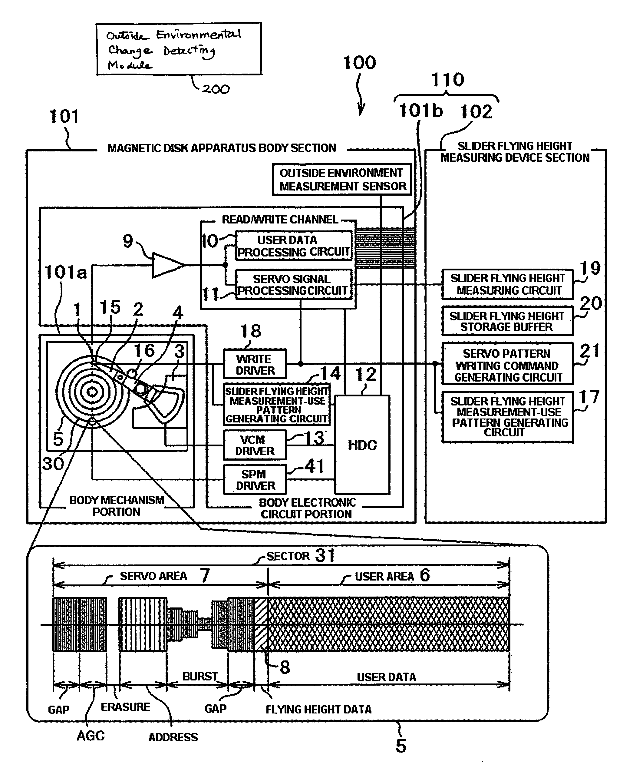
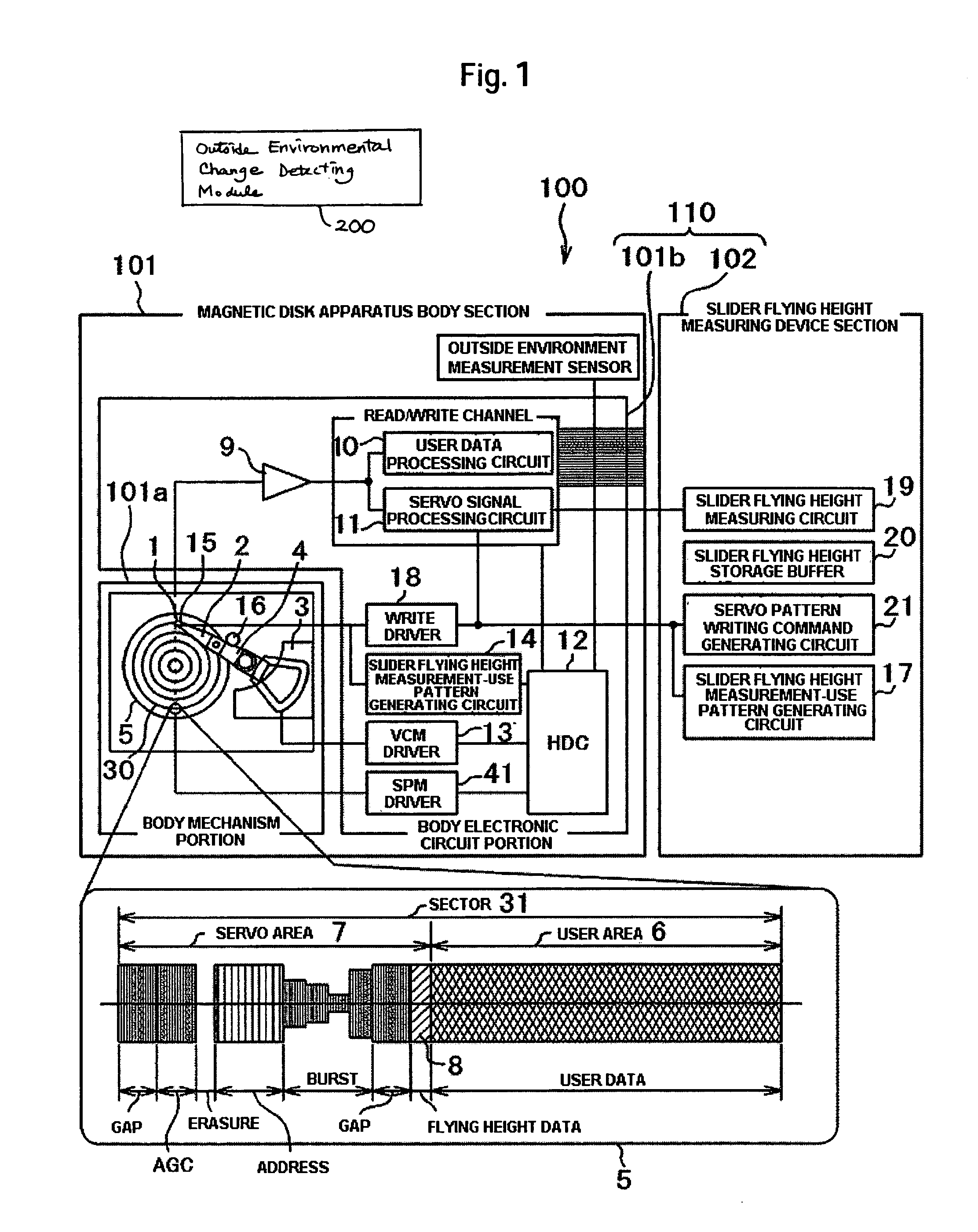
[0031]A magnetic disk apparatus and a control method thereof pertaining to an embodiment of the invention will be described below using FIGS. 1 to 6. First, the entire magnetic disk apparatus of the present embodiment will be described with reference to FIG. 1. FIG. 1 is a configural diagram of a magnetic disk apparatus 100 pertaining to the embodiment of the invention.

[0032]The magnetic disk apparatus 100 includes a magnetic disk apparatus body section 101 and a slider flying height measuring device section 102. The magnetic disk apparatus 100 also includes a magnetic disk 5 disposed with tracks 30 including servo areas 7 for recording servo data and user areas 6 for recording user data, a magnetic head slider 1 disposed with a magnetic head (not shown) that flies over the rotating magnetic disk 5 and records data to the magnetic disk 5 or plays back data recorded on the magnetic disk 5, and a control device 110 that controls the operation of the apparatus.

[0033]The magnetic disk a...


PUM

PropertyMeasurementUnit
flying heightaaaaaaaaaa
operational time constantaaaaaaaaaa
temperatureaaaaaaaaaa

Abstract

Embodiments of the invention enable the flying of a slider to be lowered and increase recording density with a simple configuration in a magnetic disk apparatus. In one embodiment, a magnetic disk apparatus comprises a magnetic disk including tracks for recording data; a magnetic head slider disposed with a magnetic head that flies over the rotating magnetic disk and records data to, or plays back data from, the magnetic disk; and a control device that controls the operation of the apparatus. Slider flying height data that vary inside the tracks are prerecorded in the tracks of the magnetic disk. The control device controls the operation of the magnetic head slider with respect to the magnetic disk on the basis of the slider flying height data recorded in the tracks.

Description

CROSS-REFERENCES TO RELATED APPLICATIONS[0001]This application claims priority from Japanese Patent Application No. JP2004-253944, filed Sep. 1, 2004, the entire disclosure of which is incorporated herein by reference.BACKGROUND OF THE INVENTION[0002]The present invention relates to a magnetic disk apparatus and a control method thereof, and is particularly suitable for a magnetic disk apparatus disposed with a magnetic head slider that operates by flying over a rotating magnetic disk and a control method thereof.[0003]With respect to magnetic disk apparatus, methods have been proposed in recent years which measure the flying height of a slider using a playback signal from a magnetic head slider or information obtained at the time of signal playback by a magnetic head. For example, in the method of measuring the flying height of a slider disclosed in U.S. Pat. No. 4,777,544 (Patent Document 1), data for measuring the flying height of a slider are recorded in a data area of a magneti...

Claims


Application Information

Patent Timeline
Patent Type & Authority Patents(United States)
IPC IPC(8): G11B21/02G11B27/36G11B5/02
CPCG11B5/455G11B5/58G11B5/6005G11B27/36G11B2220/20G11B5/5534G11B5/6029
Inventor SHIMIZU, YUKITANAKA, HIDEAKITOKUYAMA, MIKIOXU, JUNGUO
Owner HITACHI GLOBAL STORAGE TECH NETHERLANDS BV
Why Eureka
Try Eureka