Optical cable fixing structure

a technology for fixing structures and optical cables, which is applied in the direction of cables, cables laying apparatus, instruments, etc., can solve the problems of difficult to achieve sufficient fixing strength and difficult small-diameter formation of optical fibers per se, and achieve the effect of sufficient strength and sufficient strength

Inactive Publication Date: 2007-09-18
AUTONETWORKS TECH LTD +2
View PDF18 Cites 5 Cited by
  • Summary
  • Abstract
  • Description
  • Claims
  • Application Information

AI Technical Summary

Benefits of technology

[0017]According to various exemplary embodiments of the invention, the positions of engaging the pairs of engaging pieces and the jacket differ from each other in the peripheral direction of the optical cable for the respective stoppers and therefore, a force of fixing the jacket is dispersed in the peripheral direction and the optical cable can be fixed with a sufficient strength. Particularly, even when the respective stoppers are proximately arranged, the force of fixing the jacket by the respective stoppers is dispersed in the peripheral direction of the jacket and therefore, the optical cable fixing portion structure is effective in that the optical cable can be fixed with a sufficient strength.
[0018]Further, according to some exemplary embodiments of the invention, the plurality of stoppers are contiguously arranged in the longitudinal direction of the optical cable and therefore, compact formation of a structure a portion of fixing the structure can be achieved.
[0019]Further, according to some exemplary embodiments of the invention, the respective pairs of engaging pieces include the blade portions configured by the inner side faces opposed to each other and the front end faces disposed on the front end sides in the direction of pressing the pairs of engaging pieces to the both side portions of the jacket and by pressing the pairs of engaging pieces to the both side portions of the jacket, the blade portions cut into the jacket and by bringing the portions of the inner side faces opposed to each other of the engaging pieces to the cut into portions, the engaging pieces are engaged with the jacket and therefore, optical loss can be reduced by avoiding a compression force operating on the optical fiber.

Problems solved by technology

In this case, small-diameter formation of the optical fiber per se is difficult and therefore, generally, there is a tendency of achieving thin-wall formation of a jacket.
However, the above-described stopper is basically constructed by a constitution of cutting the jacket and engaging the stopper to the cut portion and therefore, when the jacket is thinned, a sufficient fixing strength is difficult to achieve.

Method used


Image

  • Optical cable fixing structure
  • Optical cable fixing structure
  • Optical cable fixing structure

Examples


Embodiment Construction

[0027]An explanation will be given an optical cable fixing portion structure according to an exemplary embodiment of the invention as follows.

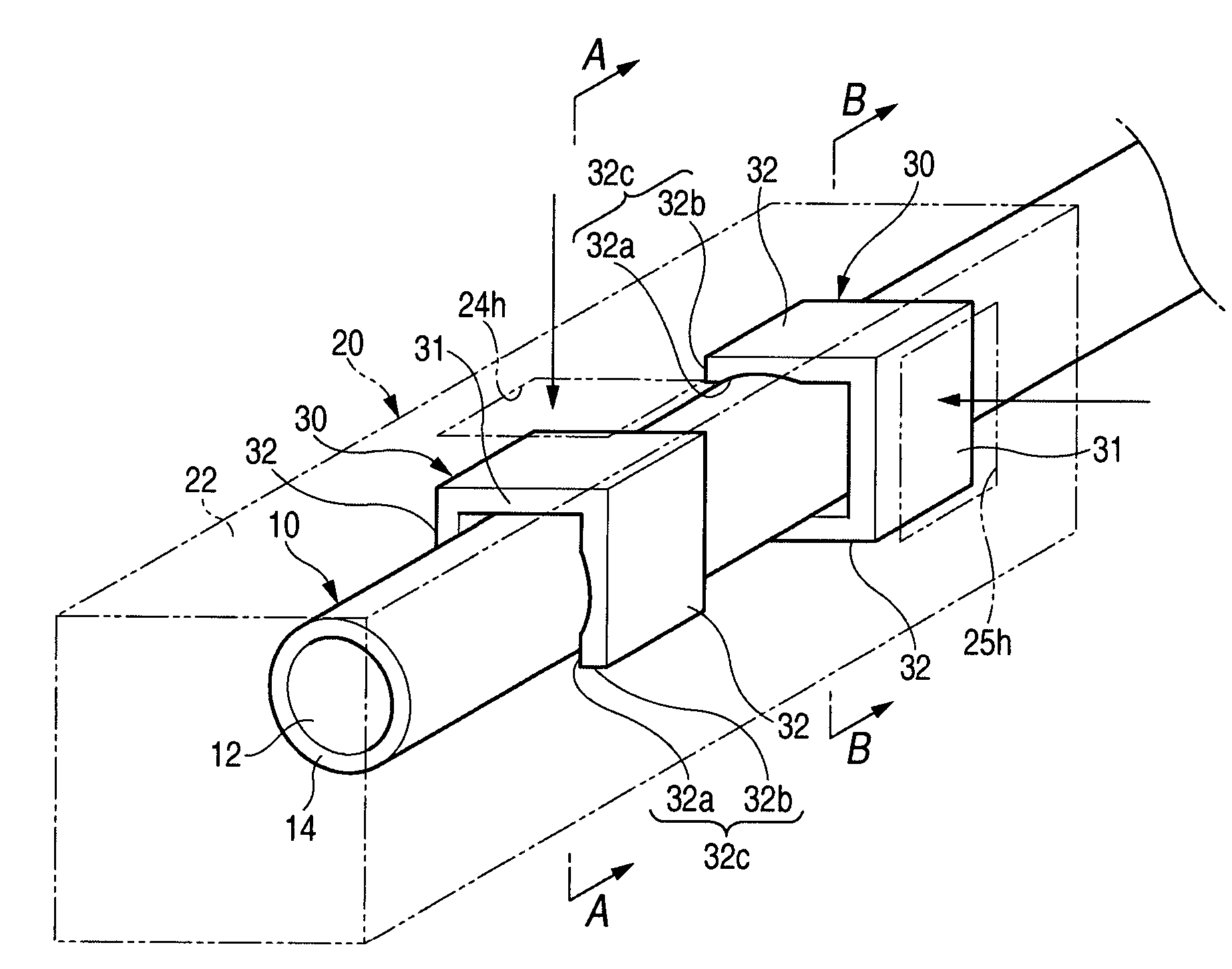
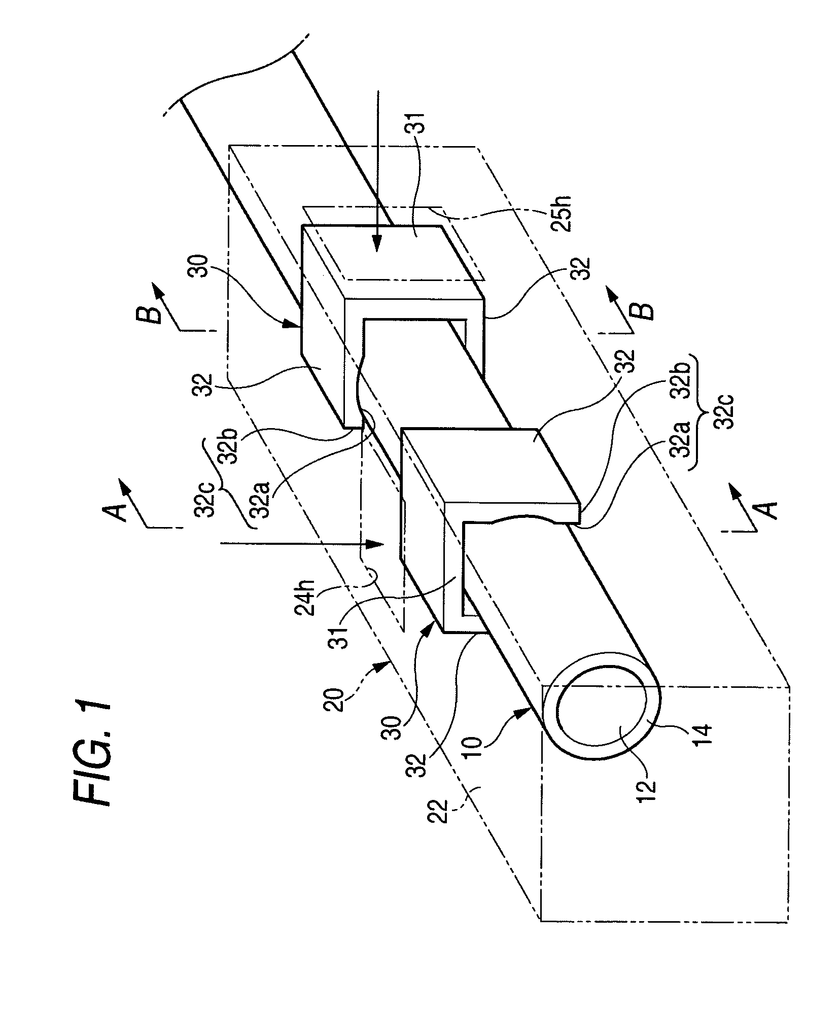
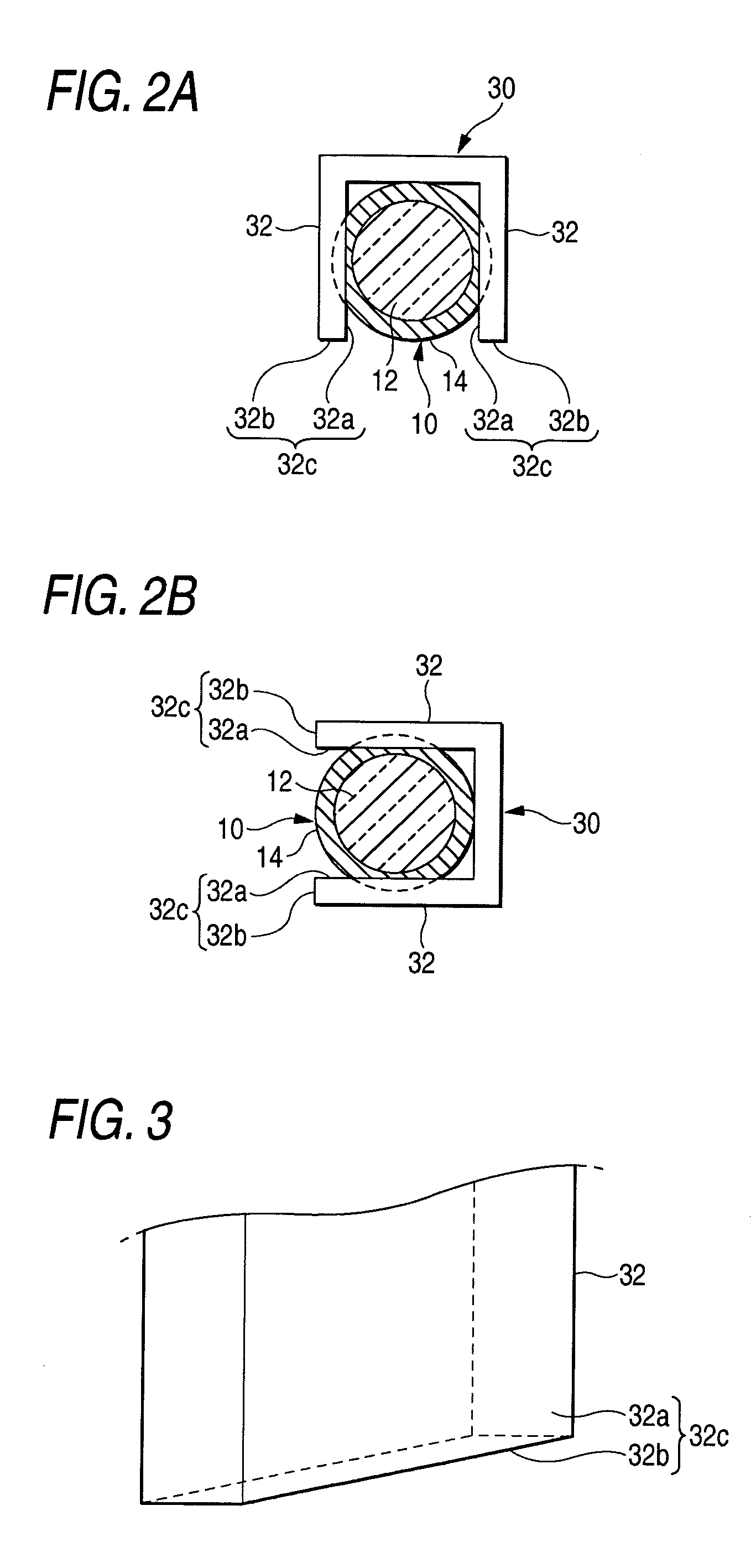
[0028]FIG. 1 is a perspective view showing an optical cable fixing portion structure, FIG. 2A is a sectional view taken along a line A-A of FIG. 1, and FIG. 2B is a sectional view taken along a line B-B of FIG. 1.

[0029]The optical cable fixing portion structure is a structure for fixing an optical cable 10 to an optical connector 20 and is provided with a plurality of stoppers 30.

[0030]The optical cable 10 is configured by covering a jacket 14 at an outer periphery of an optical fiber 12 having a core and a cladding. As a material of the jacket 14, it is preferable to use a resin having a comparatively large hardness of polypropylene species, polyamide species or the like in order to firmly engage the stopper 30, mentioned later, to the jacket 14. Further, the optical fiber 12 is exposed at a front end portion of the optical cable 10 as necess...


PUM


Abstract

Respective stoppers are engaged with a jacket at positions along a longitudinal direction of an optical cable different from each other by using a plurality of the stoppers having pairs of engaging pieces arranged in parallel with each other by an interval dimension smaller than a width dimension of the jacket of the optical cable. Further, positions of engaging the pairs of engaging pieces and the jacket may be shifted from each other by a quarter periphery in a peripheral direction of the optical cable for the respective stoppers.

Description

CROSS-REFERENCE TO RELATED APPLICATION[0001]The invention claims priority to Japanese Patent Application No. JP 2003-360197 filed on Oct. 21, 2003. The disclosure of the prior application is incorporated herein by reference in its entirety.BACKGROUND OF THE INVENTION[0002]1. Field of Invention[0003]The invention relates to a technology for fixing an optical cable used as an optical signal transmitting part in a vehicular optical communication system or the like.[0004]2. Description of Related Art[0005]As a technology of fixing an optical cable to an optical connector or an optical plug, particularly, as a technology of fixing an optical cable applied to use of an automobile, the main current is a technology of covering a ring-like member made of a metal to an optical cable to calk. Otherwise, there are a technology of making a metal piece in a U-like shape bite a jacket of an optical cable to fix, a technology of welding to bond an optical cable fixing part and an optical cable cove...

Claims


Application Information

Patent Timeline
Patent Type & Authority Patents(United States)
IPC IPC(8): G02B6/00B60R16/02G02B6/44H02G1/06H02G3/30
CPCG02B6/4471
Inventor YUUKI, HAYATO
Owner AUTONETWORKS TECH LTD
Why Eureka
Try Eureka