Determination of geophone coupling
a geophone and coupling technology, applied in the direction of instruments, structural/machine measurement, material analysis, etc., can solve the problem that the reference power spectrum may not be fully representative of a well-coupled geophone, and achieve the effect of poor coupling and quick and accurate estimation
- Summary
- Abstract
- Description
- Claims
- Application Information
AI Technical Summary
Benefits of technology
Problems solved by technology
Method used
Image
Examples
Embodiment Construction
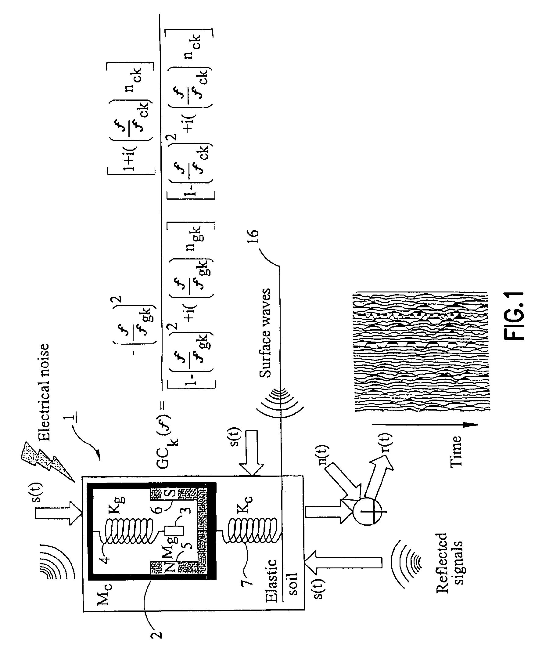
[0042]FIG. 1 is a diagrammatic view of a geophone 1. As shown in the figure, the geophone 1 comprises a casing 2. A geophone coil 3 of mass mg is suspended within the casing by a spring 4. Magnets 5,6 are disposed near the coil 3, so that movement of the coil leads to generation of an electrical current. Movements of the coil 3 are, in practice, damped, and this may be represented by a damping coefficient ηg. The geophone coil thus acts, in this model, as a classical damped harmonic oscillator.
[0043]FIG. 1 also illustrates the coupling of the geophone casing to the earth. This coupling is modelled again as a damped harmonic oscillator, and is indicated by a second spring, the “coupling spring”7, which connects the geophone casing 2 to the earth's surface 16. Damping of the coupling spring is represented by a damping coefficient ηc. The overall mass of the geophone casing 2 and its contents is denoted by mc.
[0044]A transfer function for the geophone model of FIG. 1 has been derived b...
PUM
 Abstract
Description
Claims
Application Information
 - R&D
- Intellectual Property
- Life Sciences
- Materials
- Tech Scout
- Unparalleled Data Quality
- Higher Quality Content
- 60% Fewer Hallucinations
Browse by: Latest US Patents, China's latest patents, Technical Efficacy Thesaurus, Application Domain, Technology Topic, Popular Technical Reports.
© 2025 PatSnap. All rights reserved.Legal|Privacy policy|Modern Slavery Act Transparency Statement|Sitemap|About US| Contact US: help@patsnap.com


