Electromagnetic valve

a technology of electromagnetic valves and valve bodies, applied in the direction of valve operating devices/release devices, magnetic bodies, magnets, etc., can solve the problems of increased manufacturing costs and labor hours required to design and manufacture electromagnetic valves, and achieve the effects of simplified assembly jobs, improved dimensional accuracy of iron cores, and easy design and manufacturing

Active Publication Date: 2007-09-25
SMC CORP
View PDF8 Cites 79 Cited by
  • Summary
  • Abstract
  • Description
  • Claims
  • Application Information

AI Technical Summary

Benefits of technology

[0004]An object of the present invention is to make it unnecessary to prepare two types of iron cores having a different shape by providing compatibility between a fixed iron core and a movable iron core to thereby simplify the structure of an electromagnetic valve so that the design, manufacture, and assembly jobs thereof can be executed easily as well as a manufacturing cost can be reduced.
[0010]According to the present invention, since the fixed iron core and the movable iron core are formed in the same shape and in the same size each other and have compatibility each other, when only one type of an iron core is prepared, it can be used as the fixed iron core and the movable iron core. Since iron cores need not be selected for use, an assembly job of the electromagnetic valve can be simplified. Moreover, the iron cores can be easily designed and manufactured as well as the dimensional accuracy of the iron cores can be enhanced, and parts can be easily managed, stored, and handles. As a result, the manufacturing cost of the electromagnetic valve can be reduced and the economical efficiency thereof can be enhanced.

Problems solved by technology

However, since they have a different shape according to their functions, two types of iron cores having a different shape must be prepared, and thus parts, portions, and the like relating to the iron cores must be formed in various shapes, from which a problem arises in that a long labor hour is required to design and manufacture the electromagnetic valve and a manufacturing cost is increased because the structure of the electromagnetic valve is complex.

Method used


Image

  • Electromagnetic valve
  • Electromagnetic valve
  • Electromagnetic valve

Examples


Embodiment Construction

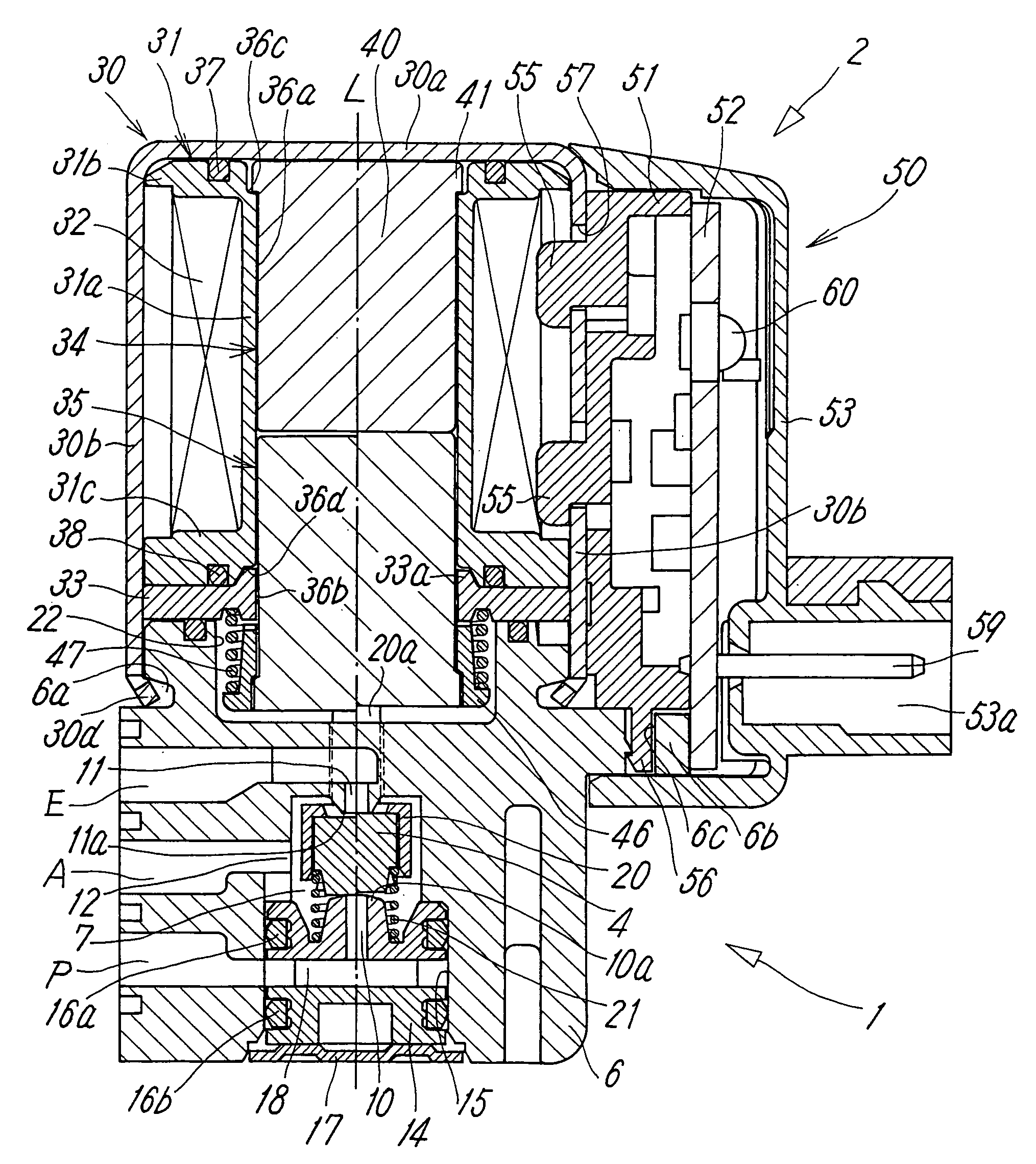
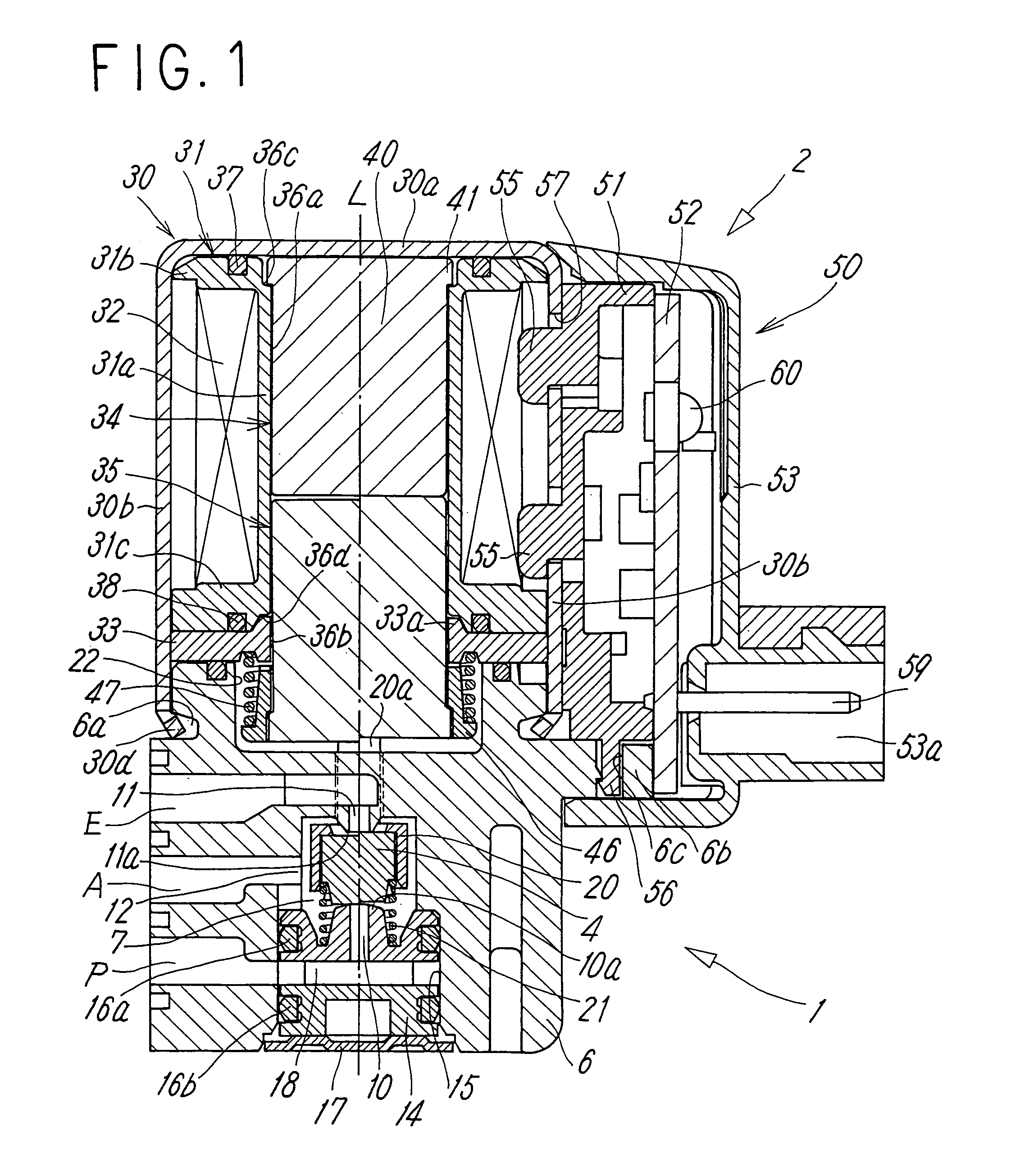
[0014]Figures show a typical embodiment of an electromagnetic valve according to the present invention. The electromagnetic valve includes a main valve portion 1 having a valve member 4 for switching a flow path and an electromagnetic manipulating portion 2 for manipulating the valve member 4, and the main valve portion 1 is coupled with the electromagnetic manipulating portion 2 in series in the axis line L direction of the electromagnetic valve.

[0015]The main valve portion 1 includes a housing 6 having a rectangular sectional shape and formed of a non-magnetic material. A supply port P, an output port A, and a discharge port E are formed on a side surface of the housing 6. A circular valve chamber 7 is formed in the housing 6 at a position on the axis line L, and the respective ports P, A, E communicate with the valve chamber 7. Among them, the supply port P and the discharge port E communicate with the valve chamber 7 at positions confronting each other, and the output port A com...


PUM

PropertyMeasurementUnit
magnetic attraction forceaaaaaaaaaa
magnetic propertiesaaaaaaaaaa
sizeaaaaaaaaaa

Abstract

An electromagnetic manipulating portion of an electromagnetic valve includes a fixed iron core fixedly disposed in the inside hole of a bobbin and a movable iron core movably disposed in the inside hole and attracted to the fixed iron core by a magnetic attraction force. The fixed iron core and the movable iron core are composed of the same normally magnetic material in the same shape and in the same size and have compatibility each other.

Description

TECHNICAL FIELD[0001]The present invention relates to an electromagnetic valve arranged to switch a valve member for switching a flow path by the action of an electromagnetic force.PRIOR ART[0002]An electromagnetic valve is ordinarily arranged such that it includes a main valve portion having a valve member for switching a flow path and an electromagnetic manipulating portion for manipulating the valve member, the electromagnetic manipulating portion includes an exciting coil wound around a bobbin, a fixed iron core for generating a magnetic attraction force by energizing the exciting coil, and a movable iron core attracted to the fixed iron core, and the valve member is switched by manipulating the movable iron core. Then, the fixed iron core is fixedly disposed in the bobbin, the movable iron core is movably disposed so as to come into contact and separate from the fixed iron core, and they have a different function.[0003]Accordingly, heretofore, the fixed iron core and the movabl...

Claims


Application Information

Patent Timeline
Patent Type & Authority Patents(United States)
IPC IPC(8): F16K31/02H01F3/00F16K11/07F16K11/044F16K31/06F16K31/08
CPCF16K31/0627F16K31/0603F16K31/0675F16K11/044H01F7/16
Inventor SATO, HIDEHARUYOSHIMURA, SHINICHI
Owner SMC CORP
Why Eureka
Try Eureka