System and method for managing data from a flow analyzer

a flow analyzer and data technology, applied in transmission systems, instruments, code conversion, etc., can solve problems such as inability to overrun buffers, and achieve the effect of increasing the number of channels

Inactive Publication Date: 2007-09-25
LUMINEX
View PDF5 Cites 68 Cited by
  • Summary
  • Abstract
  • Description
  • Claims
  • Application Information

AI Technical Summary

Benefits of technology

[0019]The problems outlined above are solved by the system and method in accordance with the present invention. Broadly, the system includes a synchronous process to write sample data to and read data from a circular buffer. Samples are synchronously clocked into and out of the circular buffers. Writing a sample into a circular buffer causes the oldest sample to be removed from the circular buffer and processed. Sample rate is thus not limited by the circular buffer size and hardware resources, e.g. FPGA, and it is possible to increase the number of channels. Because the circular data buffers fill and empty at the same rate there is no possibility of buffer overrun and lost data.
[0020]One preferred embodiment of the present invention provides a system and method of increasing the amount of data while reducing the chance of lost data in flow analyzers, flow cytometers, and other measurement devices using synchronous processes to write sample data to and read data from a circular buffer. Samples are synchronously clocked into and out of the circular buffers. Writing a sample into a circular buffer causes the oldest sample to be removed from the circular buffer and processed. It is the sampling that drives the processing keeping the write and read processes in synchronization. Dual port ram is used so there is no competition between the read and write processes. Because the write and read processes are synchronized, buffer overrun is not possible and the buffer size is determined by the data required for the specific process algorithm. Increasing the number of FADC channels (Filter, Amplify, Digitize, Convert) does not decrease the sample throughput since channels are processed in parallel. Increasing the number of samples in a process (e.g. a running sum) does not decrease throughput since the running sum is updated with each incoming sample in real time.
[0021]In one form, the data processing is split into small pipelined steps, e.g. where the pipeline processing performs the logic and arithmetic operations on the sample data. This pipeline processing of the sample data is performed by a Programmable Logic Device (PLD) such as an FPGA or ASIC at the analog-to-digital conversion (ADC) sample rate for as many channels as desired, provided the PLD has sufficient internal logic and external pins. This hardware approach permits a high sample rate limited only by the lesser of the ADC time or intrinsic propagation delay in reading the ADC. Additionally, while the number of channels is limited only by the PLD resources, adding channels does not limit speed of the instrument. Because the sample data processing is internal to the PLD, it is possible to add processing substeps to the pipeline with no effect on throughput. Finally, because sample data write and read are synchronous, the circular buffer fills and empties at the same rate with no possibility of buffer overrun or loss of data.

Problems solved by technology

Because the write and read processes are synchronized, buffer overrun is not possible and the buffer size is determined by the data required for the specific process algorithm.

Method used


Image

  • System and method for managing data from a flow analyzer
  • System and method for managing data from a flow analyzer
  • System and method for managing data from a flow analyzer

Examples


Embodiment Construction

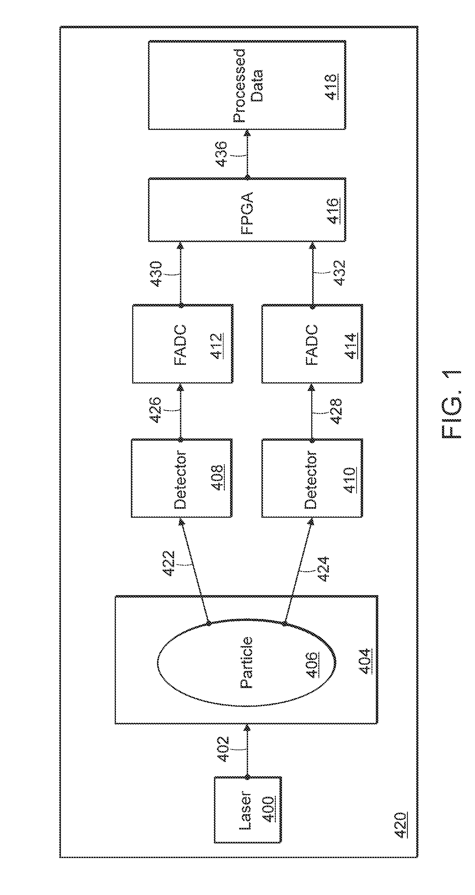
[0027]Referring to FIG. 1, a schematic is shown for a functioning flow analyzer 420, for example, a flow cytometer. Laser light beam 402 from laser 400 is shown to impinge on a particle 406 as it passes through examination zone 404 of a flow cuvette. Light 422, 424 that is scattered, emitted (for example, fluorescence emission), refracted, or otherwise produced is then sensed by one or more detectors 408, 410, which then transmit their data 426, 428 to their respective FADC (filtering, amplification, and digital conversion) units 412, 414. The FADCs then transmit 430, 432 their respective resulting digitized data to a Programmed Logic Device (PLD) such as an FPGA, ASIC or other data processor 416 for final data processing. Such a PLD is a semiconductor device having logic components for performing logic and arithmetic operations with or without combinations with processors such as DSP's. Results of processing by the FPGA or other processor 416 are then output 436 as the final, proce...


PUM


Abstract

A system and method for processing sample data employing hardware, such as a Field Programmable Gate Array (FPGA), to process the sample data in small pipelined steps. The processing includes a circular buffer where the read and write of data is synchronous, preventing buffer overrun or data loss. This pipeline processing approach allows increasing data acquisition channels or additional processing steps without limiting processing speed.

Description

PRIORITY APPLICATION[0001]This application claims priority to Ser. No. 60 / 628,715 entitled “System and Method for Managing Data from a Flow Analyzer” filed Nov. 17, 2004.BACKGROUND OF THE INVENTION[0002]1. Field of the Invention[0003]The present invention relates generally to an apparatus for, and a method of, increasing the quantity of information obtained from flow analyzers or other data collection devices by storing data relating to, for example, particles, cells, and inter-event background noise from flow through an examination zone. In particular, the present invention relates to an apparatus for and a method of increasing the rate that florescence samples may be taken, without loss of data, by splitting the sample processing into pipelined steps and using a circular buffer, or similar buffer or temporary storage capability.[0004]2. Description of the Related Art[0005]Flow cytometry is conveniently used to quickly measure one or more optical parameters of the cells and / or part...

Claims


Application Information

Patent Timeline
Patent Type & Authority Patents(United States)
IPC IPC(8): H03M1/00
CPCG01N15/14G01N2015/1477G06F12/00
Inventor MOORE, DOUGLAS E.
Owner LUMINEX
Why Eureka
Try Eureka