
Power converter with reduced common mode voltage

a power converter and common-mode voltage technology, applied in the field of power conversion devices for outputting three-phase power, can solve the problems of increasing the cost of a motor, reducing the life of the motor, and reducing the efficiency of the power converter, so as to achieve the effect of reducing the common-mode voltag

Active Publication Date: 2007-09-25
ROCKWELL AUTOMATION TECH
View PDF8 Cites 96 Cited by
  • Summary
  • Abstract
  • Description
  • Claims
  • Application Information

AI Technical Summary

Benefits of technology

Substantially reduces or eliminates common-mode voltages, improving motor safety and efficiency while maintaining simplicity and reducing costs, as shown by the reduced voltage spectra and ripple in output phase currents.

Problems solved by technology

Consequently, running of the motor load 6 in a manner resulting in such common-mode voltages can risk damaging the motor or decrease its life expectancy.
Further, although motors can be designed with high insulation ratings such that the motors will not be harmed by such common-mode voltages, not all motors are so designed and increasing the insulation ratings of a motor can increase the cost of a motor.
Yet each of these modified power converter designs either fails to reduce common-mode voltage levels to satisfactory levels or introduces other disadvantages.
Yet such modified power converters are more complicated to operate and control, achieve their results at a cost to the power converters' modulation indices and / or THDs (total harmonic distortion levels) of voltage and current, and in any event fail to eliminate the common-mode voltages.
However, the use of additional switches can increase the complexity of controlling operation of the power converters, and can increase the cost of the power converters by increasing the number of circuit components.
Also, the use of such transformers increases the cost of the power converters and, due to the size of the transformers, can increase the bulkiness of the power converters.
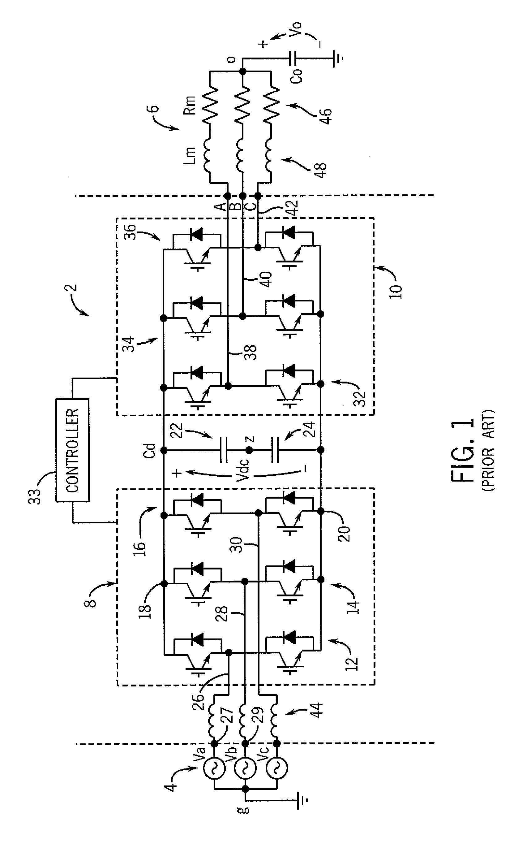
Conventionally, three-phase AC L-C filters are positioned between the inverter of the power converter and the load, e.g., three different L-C filters are implemented as part of (e.g., in series with) the output nodes 38, 40 and 42 between the IGBTs 32, 34 and 36 and the load 6 shown in FIG. 1, in association with each of the different phases A, B, and C. While the use of such filters does succeed in reducing the levels of common-mode voltages, the filters do not necessarily achieve desired reductions, particularly insofar as the filters associated with each of the different phases A, B, and C do not necessarily operate in a collective manner that might address imbalances between the common-mode voltages at the different phases A, B, and C.

Method used


Image

  • Power converter with reduced common mode voltage
  • Power converter with reduced common mode voltage
  • Power converter with reduced common mode voltage

Examples


Embodiment Construction

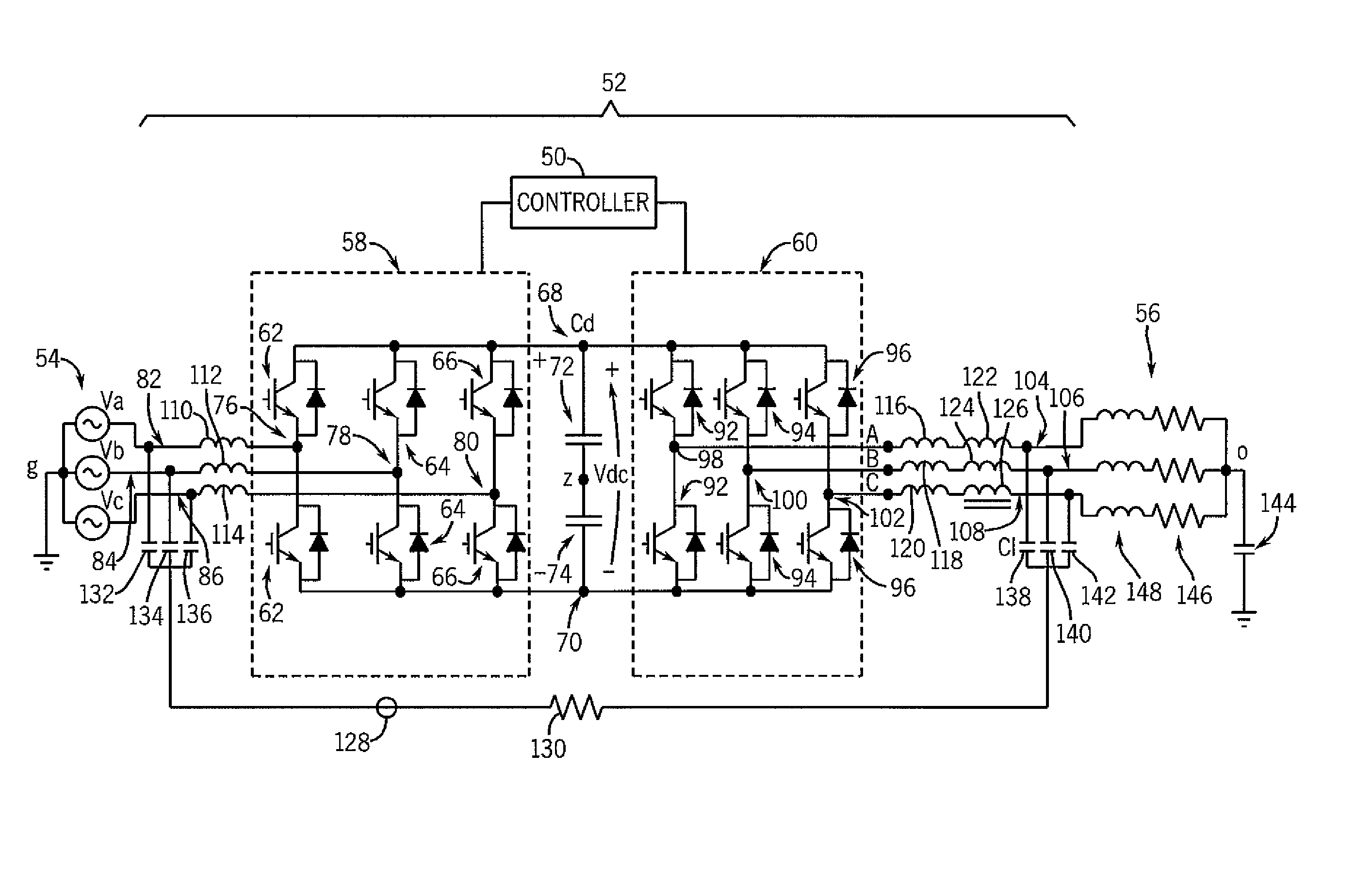
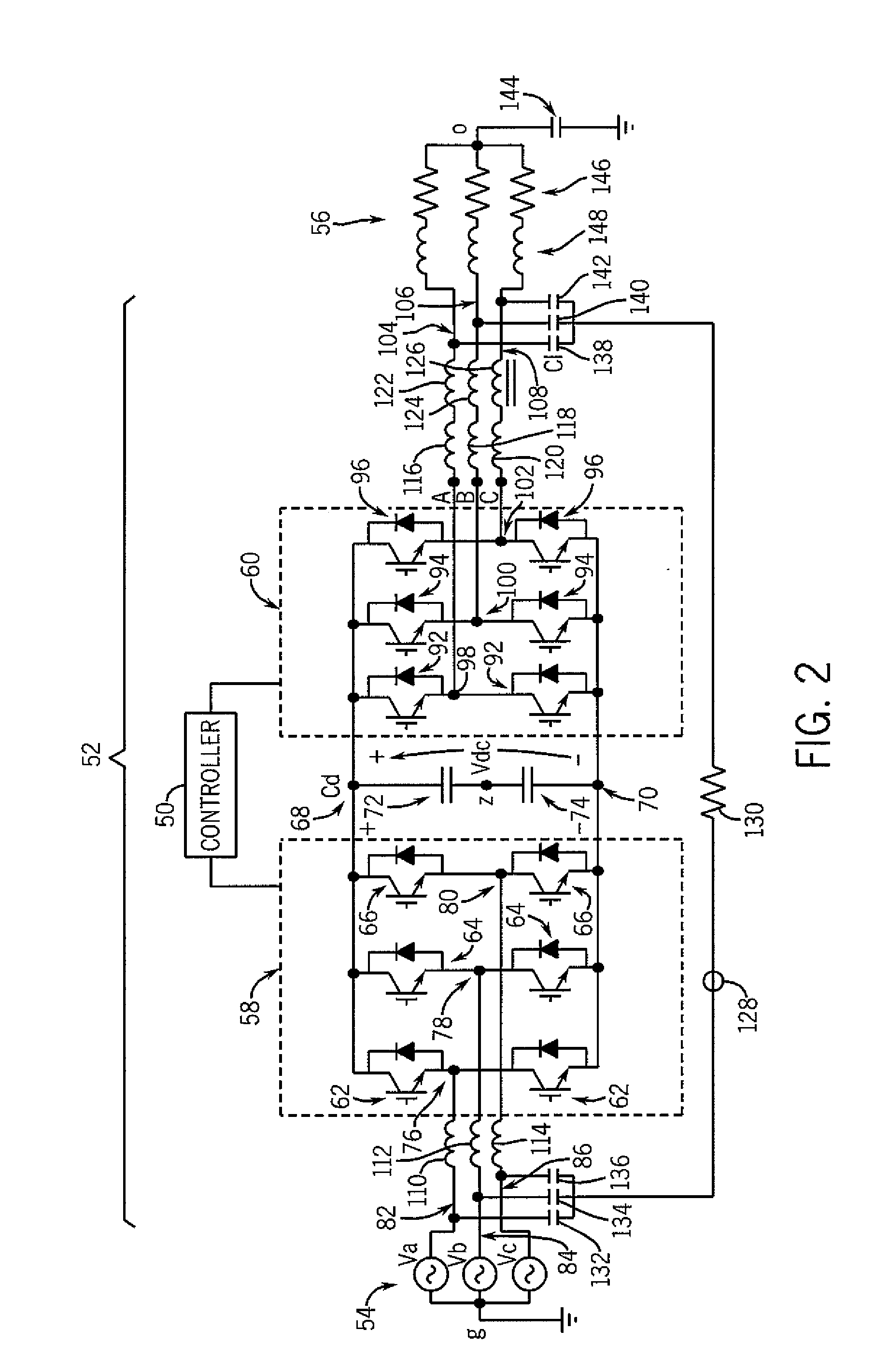
[0022]Referring to FIG. 2, a schematic is provided of a first exemplary improved power converter 52 that is coupled to a three-phase AC voltage source 54 and a three-phase load 56. In the present embodiment, the power converter 52 is a voltage source inverter (VSI) that, as described in further detail below, includes a first stage that is a rectifier 58 and a second stage that is an inverter 60. The three-phase AC voltage source 54 is intended to be representative of a variety of AC voltage sources that could provide first, second and third phases of AC electrical power to the power converter 52 including, for example, a utility / power line or other voltage source, and is modeled as three separate voltage sources Va, Vb, and Vc. In the embodiment shown, the load 56 is a three-phase AC motor (e.g., an induction or synchronous motor), and is modeled as three resistors 146 respectively in series with three inductors 148 that represent three different windings of the motor, respectively....


PUM


Abstract

An improved power converter that produces reduced-levels of common-mode voltages, or even entirely eliminates such voltages, is disclosed herein, along with a method of reducing common-mode voltages. In at least some embodiments, the improved power converter is equipped with common-mode filter inductors and a link coupling input and output ports of the power converter with one another to communicate a ground point associated with the input ports of the converter (and the source) to the load. Further, in at least some embodiments, the method includes providing common mode filter inductors as part of the converter, where the inductors are connected at least indirectly to at least one of a rectifier and an inverter of the converter, and communicating a grounded neutral from input ports of the converter to output ports of the converter by way of at least one additional linkage.

Description

FIELD OF THE INVENTION[0001]The present invention relates to power conversion devices and, more particularly, to power conversion devices for outputting three-phase power that can be used by three-phase devices such as motors.BACKGROUND OF THE INVENTION[0002]A variety of power conversion devices capable of providing a variety of types and levels of power for a variety of different purposes are now available on the market. A number of these power conversion devices are designed to output three-phase, alternating current (AC) electrical power for use by three-phase AC machines and other devices. For example, in the field of electric motors and motor drives, a three-phase AC motor can be connected to a motor drive, which includes (and operates as) a power converter and provides three-phase AC electrical power to the motor in a controlled fashion. By controlling the currents (and voltages) applied to a given motor, the motor drive further is capable of controlling motor speed, torque an...

Claims


Application Information

Patent Timeline
Patent Type & Authority Patents(United States)
IPC IPC(8): H02M1/12H02J3/01
CPCH02M1/44H02M5/4585
Inventor ZARGARI, NAVID REZARIZZO, STEVEN CARMENXIAO, YUANWU, BIN
Owner ROCKWELL AUTOMATION TECH
Learn More