Harmonic diagnosing method for electric facility

a technology of electric equipment and harmonic diagnosis, applied in the direction of mechanical measurement arrangement, mechanical roughness/irregularity measurement, instruments, etc., can solve the problems of high diagnostic cost including the measuring device, measurement takes time, and abnormality and deterioration, and achieves a simple diagnosis method

Active Publication Date: 2007-09-25
ZHONGKUANG LONGKE ENERGY TECH BEIJING
View PDF4 Cites 6 Cited by
  • Summary
  • Abstract
  • Description
  • Claims
  • Application Information

AI Technical Summary

Benefits of technology

[0029]The harmonic diagnosis method for electric equipment according to the present invention is performed by measuring the current harmonics flowing into the electric motor and inverter, however, this method does not depend on the capacities of the electric motor or inverter. This method is also irrespective of power source impedance, load factor, the parallel equivalent capacity of the load of other than these devices, the service voltage, the types of harmonic measures and the like, thereby being an extremely simple diagnosis method.
[0030]Furthermore, the relation between the harmonics and the deteriorated part of the electric motor and inverter has been clarified by using a basis analytical method. Since it becomes possible to distinguish between the degrees of deterioration based on the basis analytical method, the method of harmonic diagnosis according to the present invention is extremely practical, with the potential of spreading to the industrial society.

Problems solved by technology

Since its installation affects the precision of an electric motor, the pickup must be fixed near the source of vibration.
In addition, the location of an abnormality and deterioration to be diagnosed is restricted to mechanical elements such as bearings and rotary shafts.
Furthermore, the measurement takes time, and the diagnosis cost including the measuring device is expensive.
Unlike vibration methods, all these methods cannot determine the cause and location of an abnormality and deterioration, and above all, online survey systems, which can diagnose abnormal load only, are extremely expensive.
This is extremely troublesome, time consuming, and costly.

Method used


Image

  • Harmonic diagnosing method for electric facility
  • Harmonic diagnosing method for electric facility
  • Harmonic diagnosing method for electric facility

Examples


embodiment

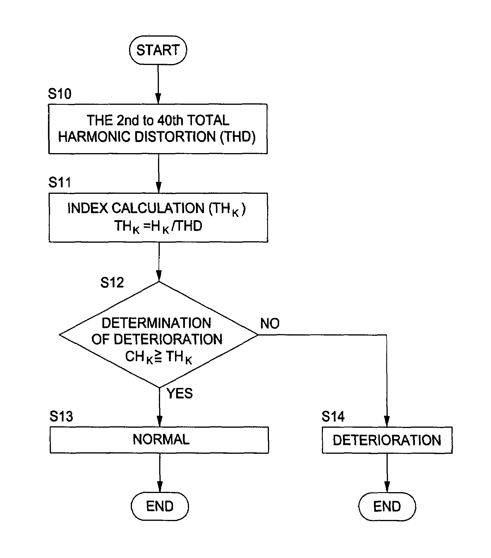
[0091]As the embodiment of the present invention, the calculated value for diagnosis and the Kth-order harmonic function which are necessary for the deterioration determination of the electric motor and inverter will be described as follows by taking up specific examples. However, the present invention is not limited to this embodiment. In the following description, Hk is the Kth-order harmonic content.

[0092](1) Diagnosis of the electric motor (diagnosis of the electric motor's main body). When K=2, 3, 4 or 5, Σ takes K=2 to 5. The procedure to find Ck is as follows.

Mo=(ΣH2k)1 / 2  1

Ak=Hk / Mo  2

ToΣAk  3

Ck=Ak / To  4

[0093]On the other hand, f(Mk) can be the following values. In the following numerical formulas, Ik represents the index value of the kth-order harmonics.

f(M2)=S1×(ΣIk−I32)

f(M3)=S2×(ΣIk−I33)

f(M4)=S1×(ΣIk−I4)

f(M5)=S2×(ΣIk−I35)

[0094]In the case of the inverter-driven motor, S1=S2=1.0, and in the case of the electric motor alone (no inverter), S1=1.15 and S2=1.25.

[0095](2) Diagno...


PUM


Abstract

The present invention relates to a method of diagnosing deterioration by comparing an index value which is obtained by dividing the relative harmonic content of each order of the current harmonics flowing into an electric motor and inverter by the total harmonic distortion of the current harmonics up to the predetermined order, with a criteria value which is obtained by multiplying a harmonic function of each order formed of the index value by a calculated value for diagnosis of each order found through calculation from the relative harmonic content of each order. In the method, the degrees of deterioration of the electric motor and inverter are distinguished from each other by weighting the criteria value, and the deteriorated part is determined by a specific harmonic order of the current harmonics.

Description

CROSS REFERENCE TO RELATED APPLICATIONS[0001]This application claims priority to International Application No. PCT / JP2004 / 001154, filed Feb. 4, 2004, entitled HARMONIC DIAGNOSING METHOD FOR ELECTRIC FACILITY, which claims priority to Japanese Patent Application No. 2003-36362, filed Feb. 14, 2003, entitled METHOD OF HARMONIC DIAGNOSIS FOR ELECTRIC EQUIPMENT, which claims priority to Japanese Patent Application No. 2003-30807, filed on Feb. 7, 2003, entitled METHOD OF HARMONIC DIAGNOSIS FOR ELECTRIC EQUIPMENT, all of the above disclosures are incorporated herein by reference in their entirety.BACKGROUND OF THE INVENTION[0002]1. Field of the Invention[0003]The present invention belongs to the technical field of electric equipment diagnosis, and relates to a method of harmonic diagnosis for electric equipment such as motors and inverters.[0004]2. Description of the Related Art[0005]Recent electric equipment has been tried to improve its productivity by a continuous and integrated produ...

Claims


Application Information

Patent Timeline
Patent Type & Authority Patents(United States)
IPC IPC(8): G01R25/00G01R23/20G01R31/34G01R31/00H02M7/48H02P23/07H02P27/06H02P27/08H02P29/00
CPCH02P29/02G01R31/00
Inventor KOH, HIROSHI
Owner ZHONGKUANG LONGKE ENERGY TECH BEIJING
Why Eureka
Try Eureka