Motor manufacturing process

a manufacturing process and motor technology, applied in the direction of magnets, manufacturing tools, magnetic bodies, etc., to achieve the effect of reducing the axial length of the motor, reducing the extent of the coil bulge, and reducing the axial size of the motor

Inactive Publication Date: 2007-10-02
AISIN AW CO LTD
View PDF30 Cites 20 Cited by
  • Summary
  • Abstract
  • Description
  • Claims
  • Application Information

AI Technical Summary

Benefits of technology

[0009]There is thus a need to adopt an electric motor or a hybrid system in an automobile, wherein the axial size of the motor is reduced.
[0010]The invention thus provides a motor manufacturing process that can, among other things, reduce the bulge extents of the coil from the motor core and reduce the axial length of the motor.

Problems solved by technology

However, the following problems are included in the motor manufacturing process using the above described inserter method.
This problem, as described above, also occurs when the motor core has the coil inserted not only in the stator core but also in the rotor core.

Method used


Image

  • Motor manufacturing process
  • Motor manufacturing process
  • Motor manufacturing process

Examples


first embodiment

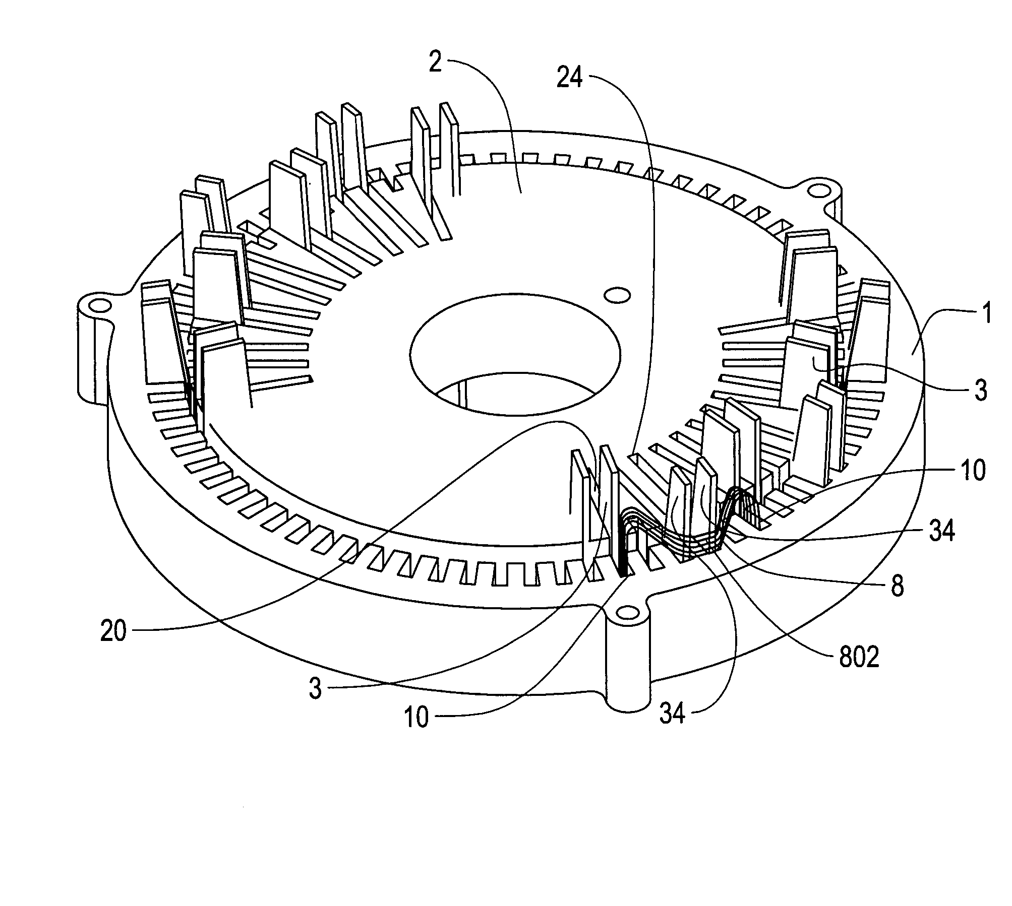
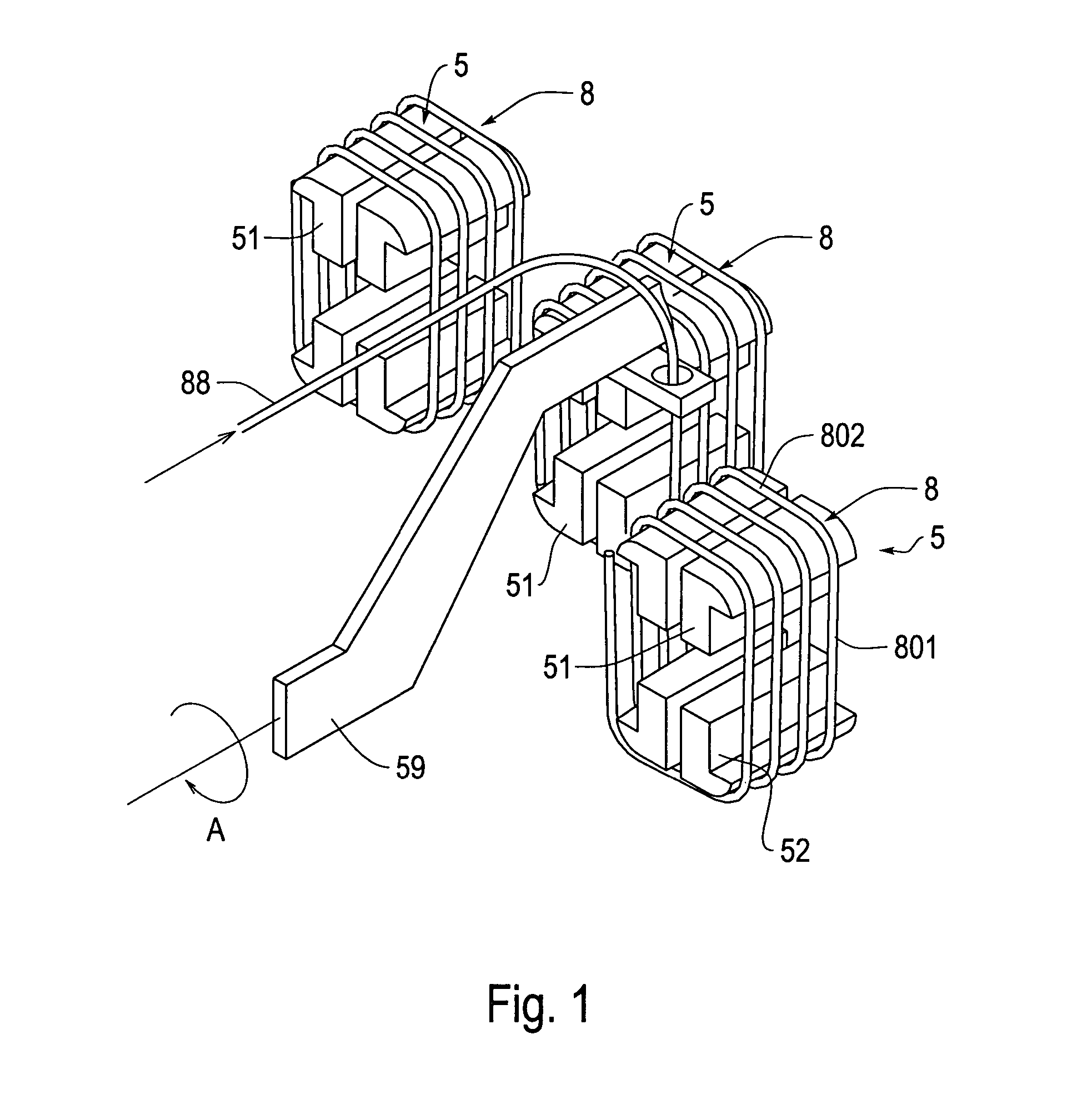
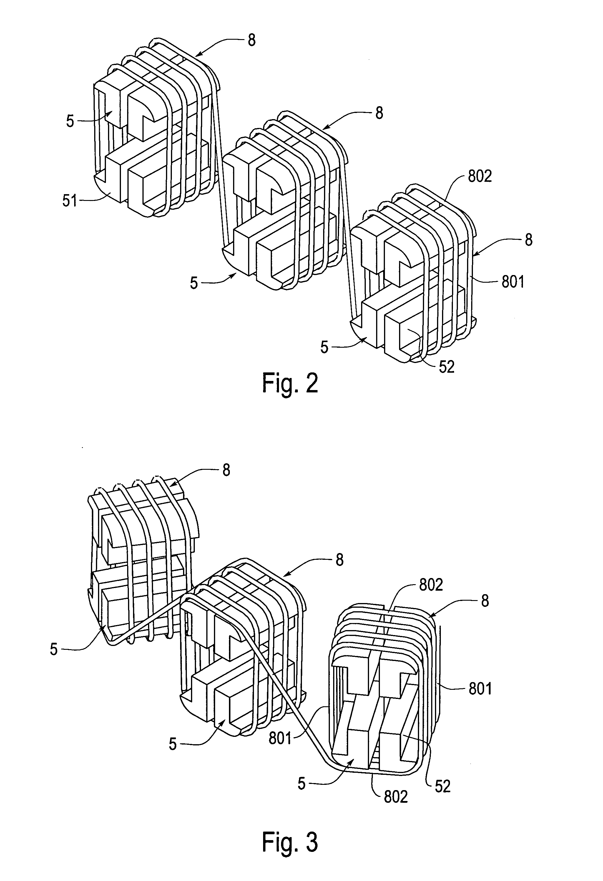
[0086]A motor manufacturing process according to the invention will be described with reference to FIGS. 1-15. A motor to be manufactured by the process of this embodiment includes: a ring-shaped motor core (or stator core) 1 (FIG. 9 to FIG. 12) having a plurality of slots 10 formed in its inner circumference; and a coil group of three phases (U-phase, V-phase and W-phase) (FIG. 16 and FIG. 17). In this motor manufacturing process, the coil group of each phase is composed of a plurality of single-pole coils 8 constructing one pole. Each single-pole coil 8 is inserted into and arranged in the stator core 1 across two slots 10. The single-pole coils 8 belonging to the coil groups of the different phases have their coil end portions 802 partially overlapping each other when they are mounted in the stator core 1.

[0087]The manufacturing process of this embodiment includes a coil forming step and a coil inserting step.

[0088]As shown in FIG. 1 to FIG. 3, the coil forming step forms the coi...

third embodiment

[0156]In the invention, another example of the aforementioned insertion blades is shown in FIGS. 20A and 20B. As shown in FIGS. 20A and 20B, specifically, an insertion blade 302 of this embodiment is formed into a generally L-shape, which is composed of a horizontally extending base portion 303 and a vertically extending vertical blade portion 304. Moreover, this vertical blade portion 304 has an abutment face 305 formed as a vertical face. And, the insertion blade 302 is constructed such that the vertical blade portion 304 is moved back and forth by moving the base portion 303 horizontally with its abutment portion 305 being kept vertical.

[0157]By using this insertion blade 302, the angle made between the coil insertion portion 801 and the axial direction of the slot core 1 can be kept substantially at 0, as shown in FIG. 20A, not only at the time of abutting against the coil insertion portion 801 but also at the instant when the insertion of the stator core 1 into the slots 10 is ...

fourth embodiment

[0158]As shown in FIGS. 21A-22C, this fourth embodiment of the invention uses a pair of upper and lower split insertion blades 320 and 330 as the insertion blades.

[0159]Specifically, the split insertion blades 320 and 330 of this embodiment are a pair of upper and lower strip shapes, as shown in FIGS. 21A-22C, and have such tapered portions 325 and 335 on one-side faces of their leading end sides as are arranged to have their leading ends in a confronting relation.

[0160]Next, the actions of the split insertion blades 320 and 330 of the case in which the single-pole coils 8 are moved will be briefly described with reference to FIGS. 21A-22C. FIGS. 21A-21C present views, in which the motions of the split insertion blades 320 and 330 and the single-pole coils 8 are taken in the radial direction of the stator core 1. FIGS. 22A-22C present explanatory views, which correspond to the individual actions of FIG. 21 and in which the width sizes of the portions, as contacting with the coils 8,...


PUM

PropertyMeasurementUnit
angleaaaaaaaaaa
angle of inclinationaaaaaaaaaa

Abstract

A plurality of single-pole coils are retained by a coil retaining device, the single-pole coils are arranged such that the coil insertion portions of each single-pole coil confront the inner circumference openings of the slots and may be generally parallel to the axial direction of the motor core, each single-pole coil is moved linearly toward the motor core such that the coil retaining device and the moving locus before the adjoining coil insertion portions in the adjoining single-pole coils are inserted into the slots are parallel or approach the more from the inner circumference side to the outer circumference side and the two coil insertion portions of each single-pole coil are moved such that they may start their movements simultaneously and at equal velocities.

Description

[0001]This application is the U.S. National Stage of PCT / JP03 / 09699 filed Jul. 30, 2003 which claims priority from JP2003-023222 filed Jan. 31, 2003 and PCT / JP02 / 07749 filed Jul. 30, 2002, the disclosures of which are incorporated herein in their entireties by reference thereto.BACKGROUND OF THE INVENTION[0002]1. Field of Invention[0003]The invention relates to a process for manufacturing a motor and, more particularly, to a process for inserting a coil into a motor core.[0004]2. Description of Related Art[0005]The motor manufacturing process of a motor with a stator prepared by inserting a coil into slots of a motor core, such as a stator core or rotor core, is important. A variety of coil inserting processes or apparatus have been proposed.[0006]In the coil inserting process of JP-A-2000-125522; JP-A-2000-116078; and JP-A-9-322492, for example, the so-called “inserter method” is used. A brief description of one example of the inserter method will be described with reference to FIG...

Claims


Application Information

Patent Timeline
Patent Type & Authority Patents(United States)
IPC IPC(8): H02K15/00H02K15/04H02K15/06
CPCH02K15/0037H02K15/0457H02K15/066Y10T29/53161Y10T29/53152Y10T29/49071Y10T29/53143Y10T29/49009Y10T29/49073H02K15/0442
Inventor KUROYANAGI, TOORUYAMAGUCHI, TSUYOSHIHASHIMOTO, SHINGOKIDO, TAKAHIRO
Owner AISIN AW CO LTD
Why Eureka
Try Eureka