Tightening torque measuring unit and torque indicating tightening device

a technology of torque measurement unit and torque indicator, which is applied in the direction of force/torque/work measurement apparatus, manufacturing tools, instruments, etc., can solve the problems of large size of bridges and like large steel-frame structures, manual use of torque wrench for tightening, and many safety problems of using torque wrench

Active Publication Date: 2007-10-02
MAEDA METAL IND LTD
View PDF14 Cites 51 Cited by
  • Summary
  • Abstract
  • Description
  • Claims
  • Application Information

AI Technical Summary

Benefits of technology

[0026]Since the torque measuring unit 4 is provided with the reaction force receiver 22, the reaction force receiving arm 20 of the reaction force receiver 22 can be given a shorter length than when the receiver 22 is provided on the tightening device main body 1. For this reason, tightening torque can be properly measured, with the axes of the tightening device main body 1, the torque measuring instrument 9 and the tightening socket 21 arranged in alignment with the axis of the nut, and with the reaction force receiver 22 prevented from being knocked down by a tightening reaction force.

Problems solved by technology

The nuts used for bridges and like large steel-frame structures are large-sized, and manually using the torque wrench for tightening heavily burdens the worker.
Using the torque wrench also poses many safety problems in view of the work environment where the tool is not always easily usable and which is likely to involve, for example, an elevated site and unstable scaffolding.
This obviates all the problems as to the burden of labor for additionally tightening the nut with the torque wrench, hazard, etc.
Furthermore, the difference in length between the arms results in a difference in torque transmission efficiency.

Method used


Image

  • Tightening torque measuring unit and torque indicating tightening device
  • Tightening torque measuring unit and torque indicating tightening device
  • Tightening torque measuring unit and torque indicating tightening device

Examples


first embodiment (

FIGS. 1 to 7)

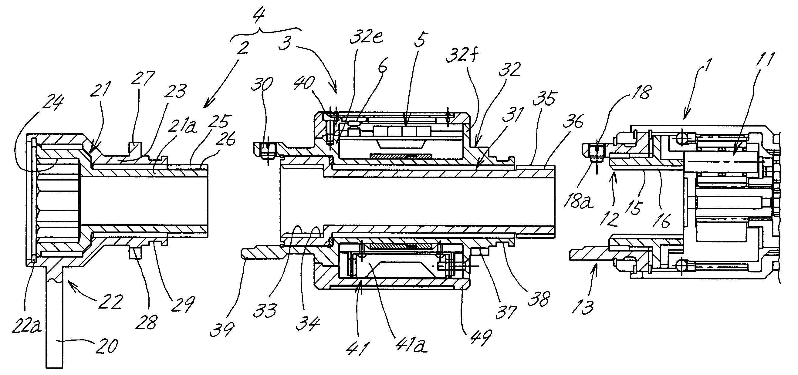
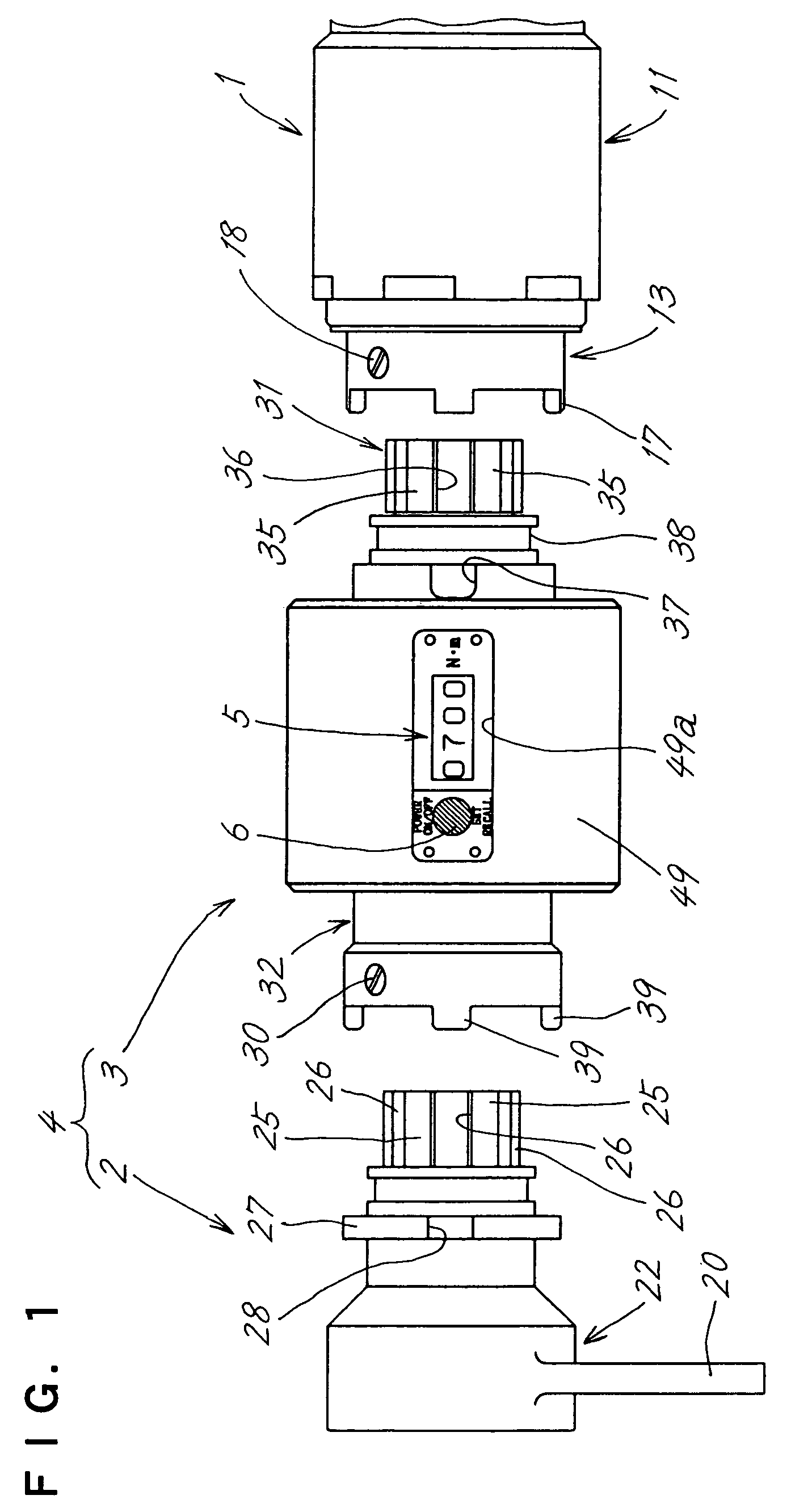
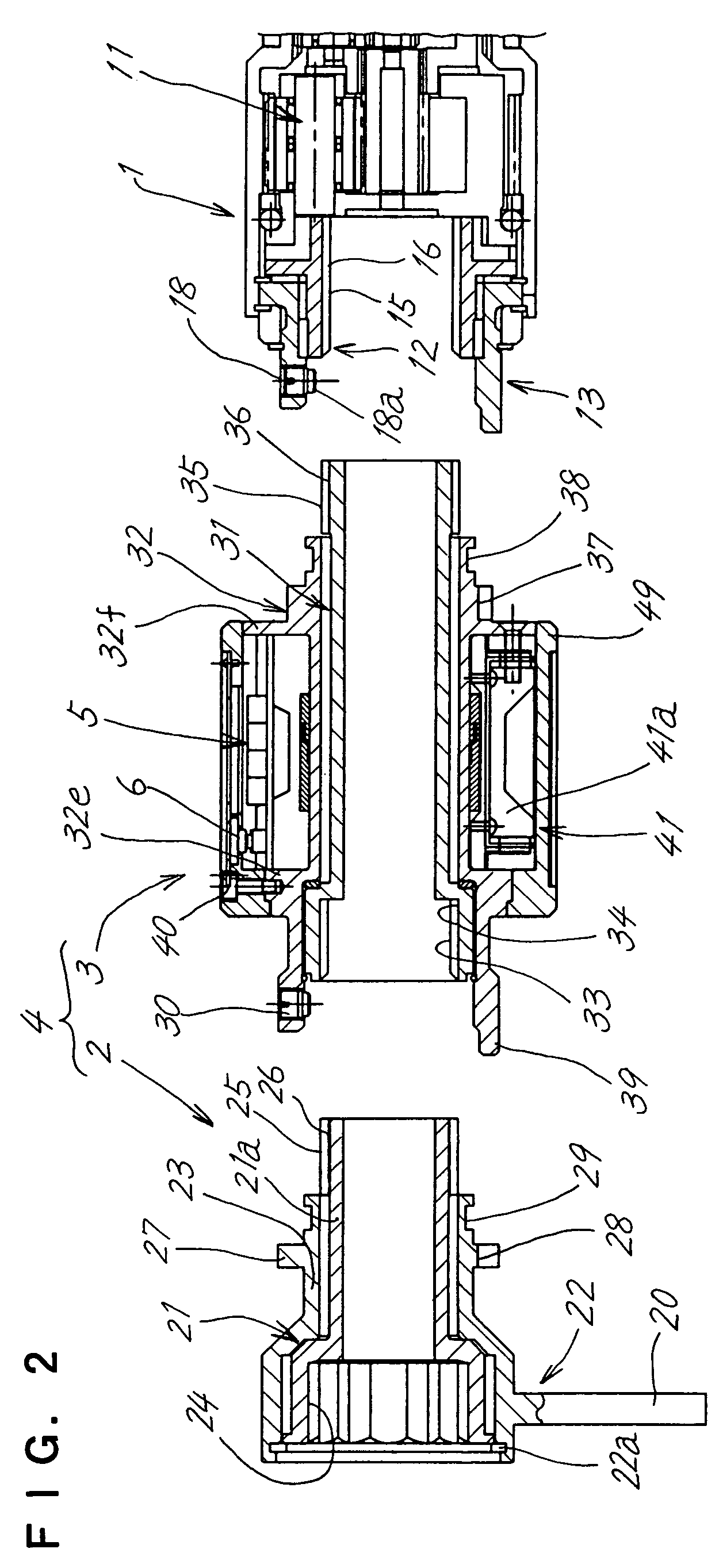
[0054]FIGS. 1 and 2 show a tightening torque measuring unit 4 as removed from a tightening device main body 1, with the measuring unit 4 further separated into a unit main body 3 and a socket unit 2. FIG. 3 shows the torque measuring unit 4 as attached to the device main body 1.

[0055]The forward end of the device main body 1 has a tubular first output shaft 12 inside and a tubular second output shaft 12 outside which is coaxial with the shaft 12. The first and second output shafts 12, 13 are coupled to a planetary gear reduction mechanism 11 so as to rotate in opposite directions to each other.

[0056]The reduction mechanism 11 is operated by a motor (not shown) incorporated in the device main body 1.

[0057]The tightening device main body 1 has a torque adjusting dial (indicated at 10 in FIG. 24) for adjusting tightening torque. The dial utilizes the fact that the value of current through the motor and the tightening torque are in a nearly proportional relationship for adj...

second embodiment (

FIGS. 8 to 10)

[0111]FIGS. 8 and 9 show a tightening torque measuring unit 4 as removed from the tightening device main body 1, and the unit 4 is shown as separated into a unit main body 3, tightening socket 21 and reaction force receiver 22. FIG. 10 shows the measuring unit 4 as attached to the device main body 1.

[0112]The device main body 1 is the same as the one already described.

[0113]The unit main body 3 of the torque measuring unit 4 differs from that of the first embodiment with respect to the outer ends of an inner shaft 31 and an outer shaft 32. The other components are the same as in the first embodiment.

[0114]The outer end of the outer shaft 32 of the unit main body 3 is in the form of a short polygonal shaft portion 32a, which is a hexagonal shaft portion according to the second embodiment.

[0115]The inner shaft 31 of the unit main body 3 has a closed outer end, which rotatably extends through the polygonal shaft portion 32a of the outer shaft 32. The outer end has a squar...

third embodiment (

FIGS. 11 to 13)

[0122]FIGS. 11 and 12 show a tightening torque measuring unit 4 as removed from the tightening device main body 1, and the unit 4 is shown as separated into a unit main body 3, tightening socket 21 and reaction force receiver 22. FIG. 13 shows the measuring unit 4 as attached to the device main body 1.

[0123]The unit main body 3, socket 21 and reaction force receiver 22 are connected in the same relation as in the second embodiment described.

[0124]The unit main body 3 is attached to the device main body 1 in a manner different from those in the first and second embodiments.

[0125]The second output shaft 13 of the device main body 1 has an outer end portion in the form of a polygonal shaft portion 13a. The first output shaft 12 of the device main body 1 has a closed outer end, which rotatably extends through the polygonal shaft portion 13a of the second output shaft 13 and provides a projecting square rod 12a.

[0126]The unit main body 3 has an outer shaft 32 having an en...


PUM


Abstract

A tightening torque measuring unit (4) has an inner shaft (31) connectable to a first output shaft (12) of a tightening device main body (1) and an outer shaft (32) connectable to a second output shaft (13) of the body. The inner shaft (31) is provided with a tightening socket (21), and the outer shaft (32) with a reaction force receiver (22). The outer shaft (32) has strain gauges (47), and an indicator (5) for converting an amount of strain detected by the gauges into a corresponding tightening torque value. Since the reaction force receiver (22) can be attached to the measuring unit (4), the tightening reaction force is prevented from acting to knock down the receiver (22), enabling the unit (4) to measure tightening torque, with the device main body (1), the measuring unit (4) and the socket (21) positioned in alignment with the axis of the nut to be tightened.

Description

FIELD OF THE INVENTION[0001]The present invention relates to a unit for measuring the tightening torque of bolt or nut tightening devices and tightening devices capable of indicating torque values.BACKGROUND ART[0002]The tightening torque of conventional bolt or nut tightening devices is adjusted and recognized by referring to a torque adjusting dial (indicated at 10 in FIG. 24) provided on the main body of the tightening device and manually tightening the bolt or nut additionally with a torque wrench.[0003]Stated more specifically, the torque adjusting dial 10 is first set at a value slightly lower than the desired tightening torque value, and a bolt or nut (hereinafter referred to typically as “nut”) is tightened.[0004]Thus, a torque value serving as a rough target value is set on the dial 10 utilizing the fact that the tightening torque of the tightening device shown in FIG. 22, Graph X and the load current of the tightening device shown in Graph Y are in a nearly proportional re...

Claims


Application Information

Patent Timeline
Patent Type & Authority Patents(United States)
IPC IPC(8): B25B23/14B25B21/00B25B23/00
CPCB25B21/00B25B23/14B25B23/0078B25B13/488G01L5/24B25B17/00
Inventor HIRAI, TATSUOKANEYAMA, YASUNOBU
Owner MAEDA METAL IND LTD
Why Eureka
Try Eureka