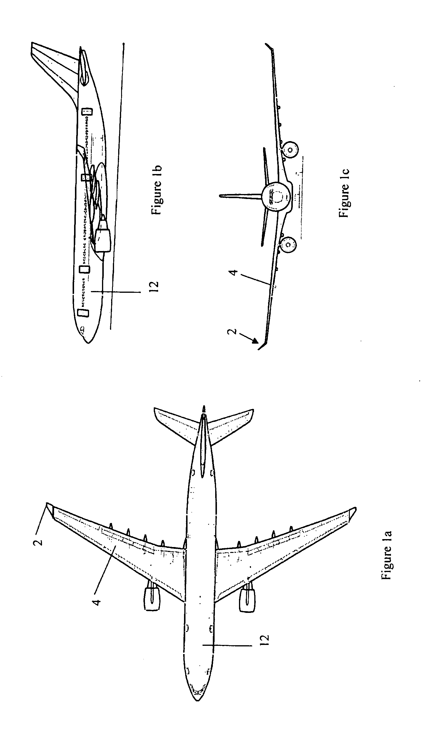
Wing tip device

a tip device and wing technology, applied in the direction of airflow influencers, influencers by generating vortices, drag reduction, etc., can solve the problems of greater aerodynamic loads on the wing and therefore greater bending moments in the wing, dictating the weight of the wing, etc., to reduce the bending moment in the wing sustained during high-load flight conditions, the maximum bending moment, and the bending moment in the wing

Active Publication Date: 2007-10-02
AIRBUS OPERATIONS LTD
View PDF67 Cites 130 Cited by
  • Summary
  • Abstract
  • Description
  • Claims
  • Application Information

AI Technical Summary

Benefits of technology

[0008]The bending moment, for example the maximum bending moment likely to be sustained, at the root of the wing sustained during high-load flight conditions may thereby be reduced. Also, the mass of the aircraft may as a result be reduced.
[0016]Alternatively, or additionally, the load generated on the wing tip device itself, when the wing tip device is in the second position, may be less than the load that would be generated on the wing tip device were the wing tip device in the first position. This may be achieved, for example, by careful design of the wing tip device toe, stalling the device or reducing its incidence.
[0022]Advantageously, the wing tip device is mounted about a hinge joint for rotational movement. A hinge joint is particularly suitable in this application, as it is able both to provide the means for rotating the wing tip device and to withstand significant loads during use.
[0030]In an embodiment of the invention described in further detail below, the movement of the device is controlled by a dedicated spring-damper system, wherein the spring and damper system is so arranged as to set a bending moment threshold, whereby the wing tip device is caused to move from the first position to the second position only when the bending moment threshold is exceeded. Advantageously, the spring controls the bending moment threshold and the damper is provided so as to reduce the effects of divergent behaviour or flutter. Thus, there may be provided a resilient means, such as for example a spring, which affects the movement and behaviour of the wing tip device during use. There may be provided a damping means, such as for example a damper, which affects the movement and behaviour of the wing tip device during use.
[0031]In a situation when the load on the wing is on the boundary of a high-loading case, it may be undesirable for the wing tip device to move between the first and second positions. Such movement might for example result in undesirable oscillations of the wing tip device. There may be provided a damper, for example a unidirectional damper that reduces the possibility of such oscillations. A unidirectional damper may be employed to provide substantially no resistance to the movement of the wing tip device from the first position towards the second position, but to provide resistance to the movement of the wing tip device to the first position.
[0039]There is also provided a method of flying an aircraft, wherein the bending moment in the wing sustained during high-load flight conditions is reduced by means of use of a wing tip device according to the present invention or by means of performing a method of altering the bending moment according to the present invention.

Problems solved by technology

Whilst improving aerodynamic efficiency, wing tip devices may lead, particularly during high-load conditions, to greater aerodynamic loads on the wing and therefore greater bending moments in the wing.
This in turn may dictate the weight of the wing.

Method used


Image

  • Wing tip device
  • Wing tip device
  • Wing tip device

Examples


first embodiment

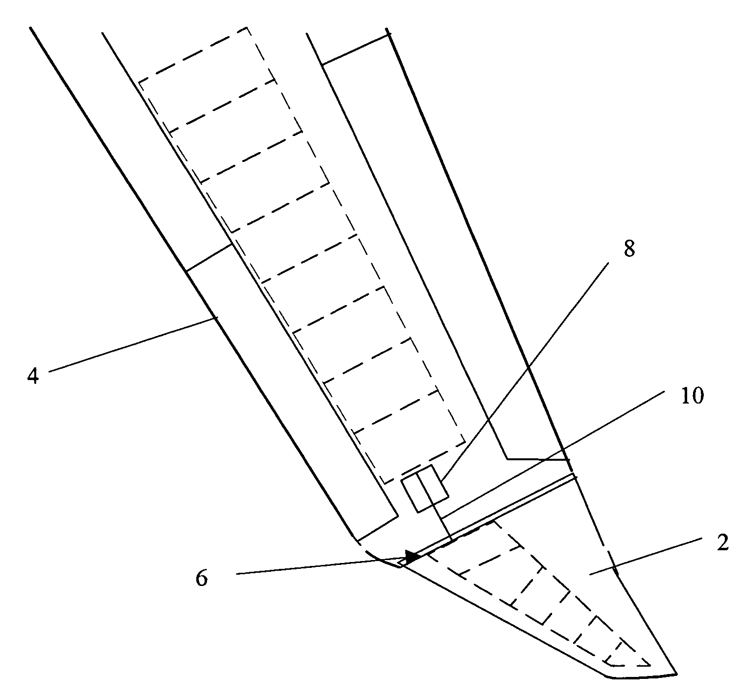
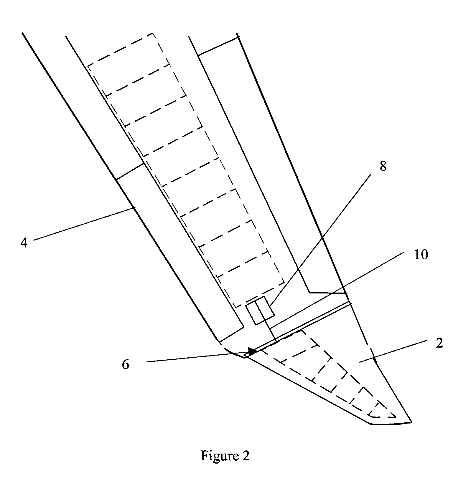
[0049]In this first embodiment of the invention, the position of the wing tip device 2 is actively controlled. When a high-load condition is detected or predicted, part of the flight controls computer sends signals that cause the rod 10 to move along the length of the wing 4 and away from the fuselage 12. The wing tip device 2 is constrained to pivot about the hinge 6 on the upper surface of the main wing 4. The action of the rod 10 therefore causes upward rotation of the wing tip device away from its first position 2a.

[0050]The airflow over the tip region of the wing 4 is disturbed, resulting in a loss of upward lift, a reduction in effective span and hence a reduction in bending moment at the root of the wing 4. Furthermore, the alignment of the hinge 6 is such that the mean incidence of the wing tip device 2 is reduced, decreasing the upward lift generated by the device and therefore further decreasing the bending moment at the root of the wing 4.

[0051]When the high-load conditi...

second embodiment

[0054]In this second embodiment, the wing tip device 102 is held in the first position during standard flight conditions and the wing tip device is controlled through active means. In the first position, the external surfaces of the wing tip device are flush with the adjacent external surfaces of the wing. When a high-load condition is detected or predicted, the actuator rotates the drive shaft 116 anticlockwise when viewed from the wing tip, rotating the wing tip device 102 leading edge down, to the second position. In the second position the edges of the wing tip device and wing that were parallel in the first position become non-parallel and the surfaces of the wing tip device and the wing are positioned so that they are no longer flush. The airflow over the tip region of the wing 104 is disturbed, resulting in a loss of upward lift, a reduction in effective span and hence a reduction in bending moment at the root of the wing 104. Furthermore, the mean incidence of the wing tip d...

fourth embodiment

[0061]It will be appreciated that various modifications may be made to the above-described embodiments of the invention. In each embodiment the wing tip device is in the form of a winglet, but the device could of course be in the form of any wing tip device that is able to improve aerodynamic efficiency when in the first position, but might cause high bending moments on the wing of the aircraft during high-load conditions. In such a modified embodiment, the device would be moveable to a second position in which the device reduces the bending moments in the main wing, for example in high-load conditions. The function of the flexible joint of the fourth embodiment may be provided by means of the wing, a portion thereof, the wing tip device, or a portion thereof, being made from an elastomeric material or a composite material having suitable resilient (springy) properties.


PUM


Abstract

An aircraft comprises a wing tip device, for example a winglet, a raked-tip device, a wing tip fence or a planar wing extension, mounted in the region of the tip of a wing on the aircraft. The wing tip device is rotatably moveable between a first position and a second position, in which the upward lift produced by the wing or the wing tip device is reduced. During flight, the bending moment at the root of the aircraft wing therefore changes in dependence on the position of the wing tip device. The maximum bending moment in the aircraft wing sustained during high-load conditions is thereby reduced, allowing the structural mass of the aircraft to be reduced.

Description

[0001]The present invention relates to aircraft and, in particular but not exclusively, to wing tip devices for aircraft and the use thereof.BACKGROUND OF THE INVENTION[0002]Increasing aerodynamic efficiency is an important factor to be considered in commercial aircraft design. To this end a number of devices may be incorporated at the tip of wings, such as winglets, raked-tip devices, wing tip fences and planar wing extensions. Such wing tip devices are provided for purposes such as reducing the strength of the wing tip vortex, moving the wing tip vortex away from the fuselage, and / or increasing the upward lift over the tip portion of the wing.[0003]Whilst improving aerodynamic efficiency, wing tip devices may lead, particularly during high-load conditions, to greater aerodynamic loads on the wing and therefore greater bending moments in the wing. (High-load conditions may occur during, for example, turbulence or a sharp turn.) The maximum bending moment to which a wing is expected...

Claims


Application Information

Patent Timeline
Patent Type & Authority Patents(United States)
IPC IPC(8): B64C9/00B64C23/06
CPCB64C23/065Y02T50/164B64C23/072Y02T50/10
Inventor IRVING, JANDAVIES, ROBERT
Owner AIRBUS OPERATIONS LTD
Why Eureka
Try Eureka