Braking system of hybrid vehicle

a hybrid vehicle and braking system technology, applied in the direction of braking systems, braking components, transportation and packaging, etc., can solve the problems of driving wheels and loss of vehicle stability

Inactive Publication Date: 2007-10-02
NISSAN DIESEL MOTOR CO
View PDF18 Cites 15 Cited by
  • Summary
  • Abstract
  • Description
  • Claims
  • Application Information

AI Technical Summary

Benefits of technology

[0006]The required braking force in demanding the braking is obtained by the regenerative power of the motor connected to the driving wheel, and a driving force by the braking actuator which brakes the driven wheel, which prevents the braking force of a driving wheel side from being excessive, thereby to carry out a stable braking performance on vehicle travel conditions such as a frozen road on which a vehicle tends to slip.

Problems solved by technology

As a result, when a vehicle travels on a slippery road such as a frozen road, the driving wheels slip, to lose vehicle stability during vehicle braking.

Method used


Image

  • Braking system of hybrid vehicle
  • Braking system of hybrid vehicle
  • Braking system of hybrid vehicle

Examples


Embodiment Construction

[0021]A preferred embodiment of the present invention will be explained with reference to accompanying drawings as follows.

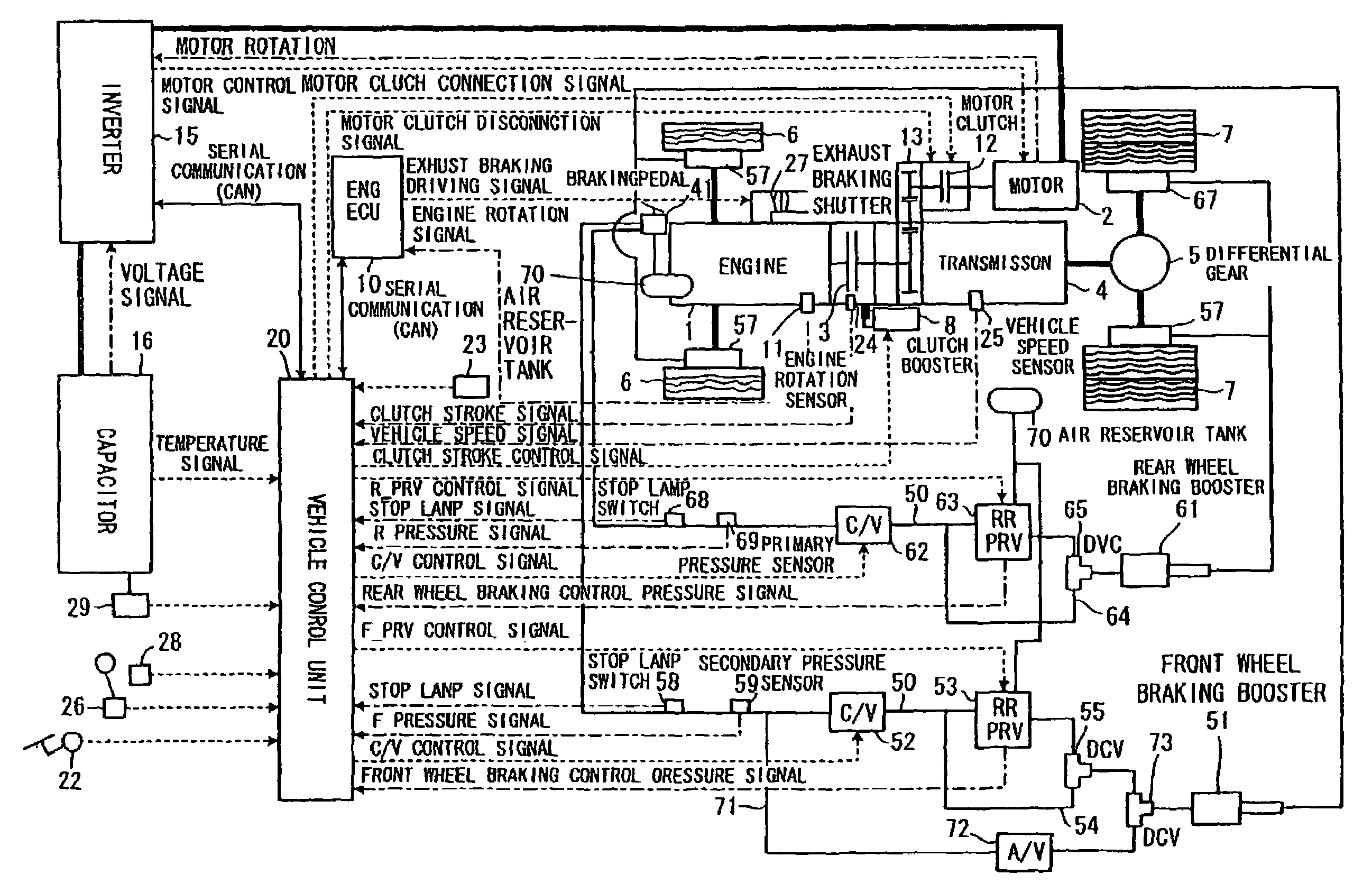
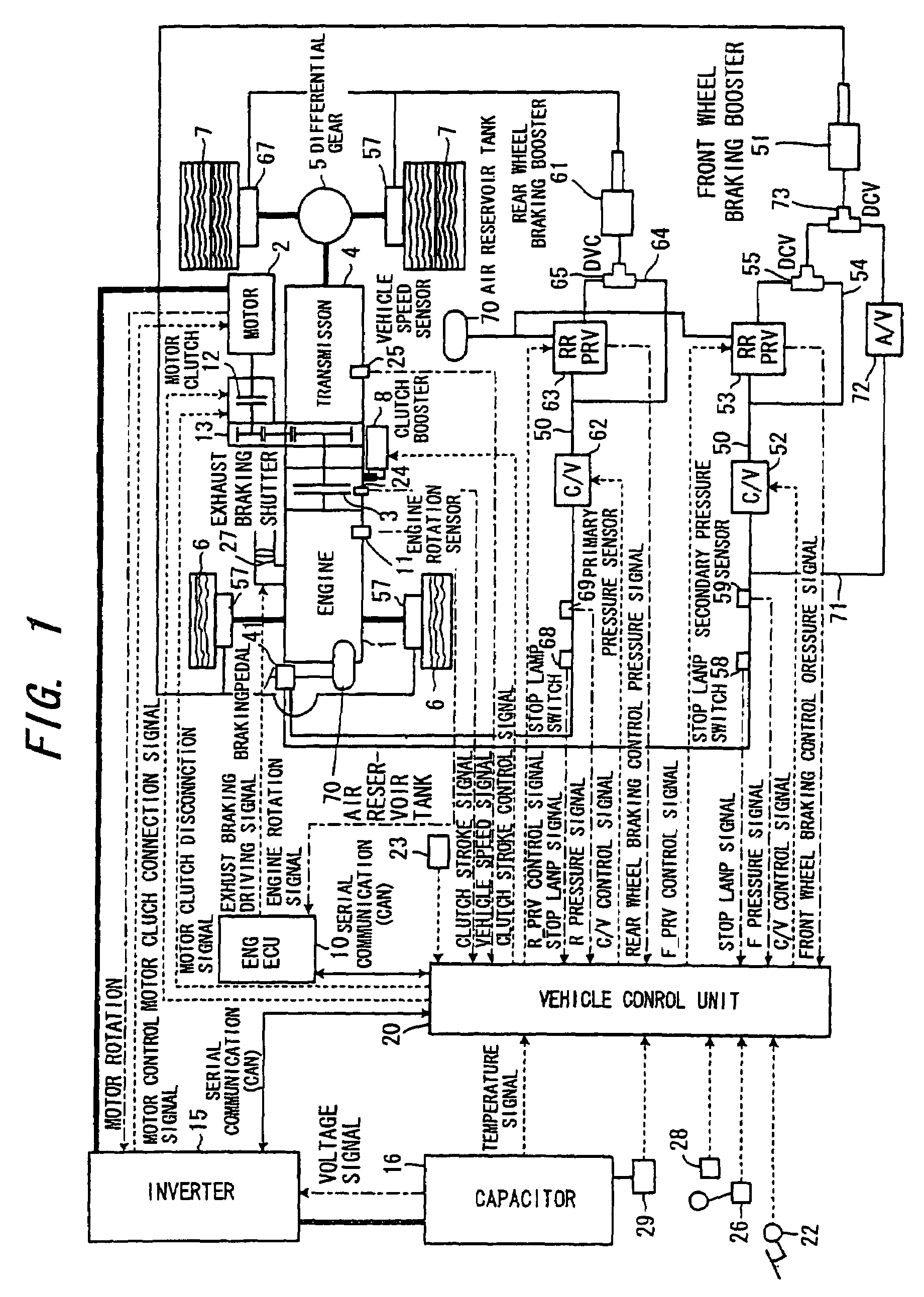
[0022]As shown in FIG. 1, a power train of a vehicle is provided with an engine 1, an engine clutch 3, and a transmission 4. An output of the engine 1 is transmitted to an input shaft of the transmission 4 through the engine clutch 3, and a rotation of an output shaft of the transmission 4 is transmitted through a propeller shaft, a differential gear 5 and a drive shaft to a right side and left side rear wheels (driving wheel) 7.

[0023]The engine 1 is an internal combustion engine which burns fuel to be supplied inside a cylinder and rotates / drives an output shaft of the engine 1 by a reciprocal movement of a piston in the cylinder.

[0024]An engine control unit 10 is provided for controlling the output of the engine 1, and controls a fuel supply amount based upon a detecting signal of an engine rotation sensor 13 or various control signals from a vehicle control u...


PUM


Abstract

A hybrid system for a vehicle which can ensure a braking stability on a slippery road is provided. Therefore, the system is provided with a motor 2 a rotation force of which is transmitted to a rear wheel 7, braking actuators 57, 67 which brake the front wheel 6 and the rear wheel 7, and proportional valves 53, 63 controlling a braking force introduced into each braking actuator 57, 67. A control unit 20 is so provided that the control unit 20 calculates a required braking energy based upon a vehicle operating condition in demanding a braking and operates the motor 2 as a power generator to generate a power so as to produce the calculated braking energy, as well as controls a braking force of the front wheel 6.

Description

TECHNICAL FIELD[0001]The present invention relates to an improvement of a braking system for a hybrid vehicle which selectively switches an engine and an electric-powered motor as a power source of a vehicle.BACKGROUND INFORMATION[0002]There is a known hybrid vehicle disclosed by Japanese Unexamined Patent Publication No. 2000-332963A which is equipped with a motor connected to an output shaft of an engine where an electric power is supplied to the motor during vehicle acceleration and operates as an electric generator during vehicle deceleration and vehicle braking for performing regenerative braking, and an accumulator is charged with a generated electric power.[0003]However, in case in such a known hybrid vehicle, during a main braking demand when a braking pedal is depressed, almost all of braking forces required are supplied by a regenerative braking based upon prioritizing the regenerative power of a motor, or the motor is operated to generate a regenerative power and at the s...

Claims


Application Information

Patent Timeline
Patent Type & Authority Patents(United States)
IPC IPC(8): B60T8/62B60K6/20B60K6/48B60W20/00B60K6/54B60L7/24B60T1/10B60T8/17B60T8/1766B60T8/26B60T13/74B60T17/04B60T17/22B60W10/08B60W10/18
CPCB60K6/44B60W10/184B60K6/52B60L7/24B60T1/10B60T8/267B60T13/74B60T17/043B60T17/22B60W10/08B60W10/18B60W30/18127B60W30/18136B60K6/48B60T2270/602B60T2270/604B60T2270/608B60W20/00B60W2520/10B60W2540/12Y02T10/6221Y02T10/623Y02T10/6265B60W2520/26B60W2720/403Y02T10/62B60W20/13B60W10/06B60W10/26
Inventor NISHINA, MITSUHIROSUZUKI, YUUJIMIYATA, TATSUJI
Owner NISSAN DIESEL MOTOR CO
Why Eureka
Try Eureka