
Occlusion-resistant catheter

a catheter and occlusion technology, applied in the field of perfusion catheters, can solve the problems of insufficient spiral configuration to keep the flow into the opening from becoming occlusion, unnecessary discomfort for patients, and limited range of spiral pathways, etc., to achieve the effect of cleaning the blood and minimizing the occlusion of the openings

Inactive Publication Date: 2007-10-02
NAVILYST MEDICAL
View PDF16 Cites 34 Cited by
  • Summary
  • Abstract
  • Description
  • Claims
  • Application Information

AI Technical Summary

Benefits of technology

[0010]Yet another aspect of the invention is a method for providing hemodialysis comprising the steps of introducing a multi-lumen catheter of this invention into a body lumen, taking in blood through the plurality of openings into a first catheter lumen; cleansing the blood by hemodialysis; and returning the blood through the second catheter lumen into the body lumen. The twisting septum, corkscrew pattern, or combination thereof in the multi-lumen catheter minimizes occlusion of the openings by the body lumen wall. Specifically, the method may comprise deploying the catheter with its distal end in or adjacent to the right atrium of the patient's heart. Where the catheter embodiment comprises a catheter tip with a corkscrew pattern and the second lumen extending distally further than a distal end of the first lumen and pointed in a direction toward the right atrium, the method may comprise returning the blood to the body lumen in a stream directed toward the right atrium.

Problems solved by technology

The '865 patent describes multi-lumen catheters having side openings located on “spiral pathways.” The ranges of these spiral pathways, however, are limited to the portions of spirals contained within two pie-shaped intake lumens that each comprise only a 90° quadrant of the circular lumen.
Thus, if there is a tendency for one circumferential portion of the catheter to be blocked and that portion happens to fall within one or both of the quadrants comprising the two intake lumens, the spiral configuration is insufficient to keep the flow into the openings from becoming occluded.
Occlusion of intake holes may reduce the intake flow significantly enough to lengthen the amount of time a patient may have to undergo the hemodialysis procedure, causing unnecessary discomfort for the patient, and causing inefficient use of resources for the dialysis provider.

Method used


Image

  • Occlusion-resistant catheter
  • Occlusion-resistant catheter
  • Occlusion-resistant catheter

Examples


Embodiment Construction

[0024]The invention will next be illustrated with reference to the figures wherein the same numbers indicate similar elements in all figures. Such figures are intended to be illustrative rather than limiting and are included herewith to facilitate the explanation of the apparatus of the present invention.

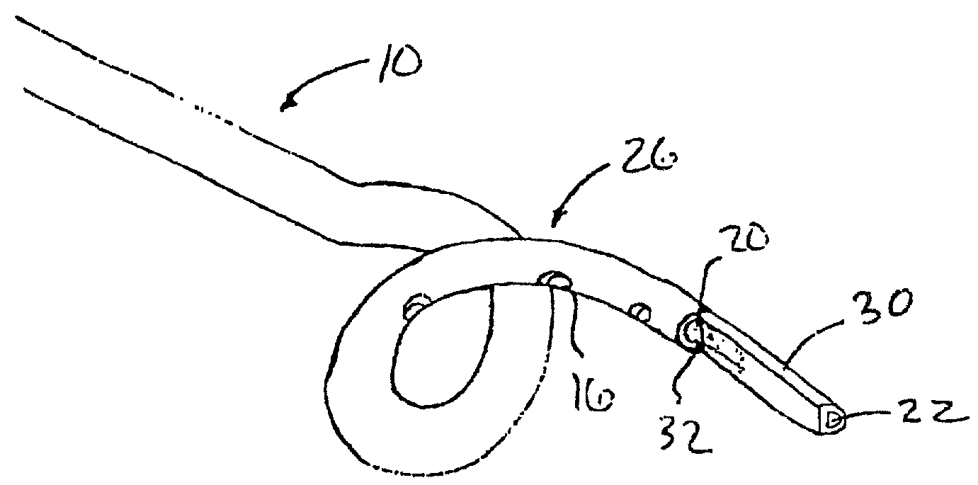
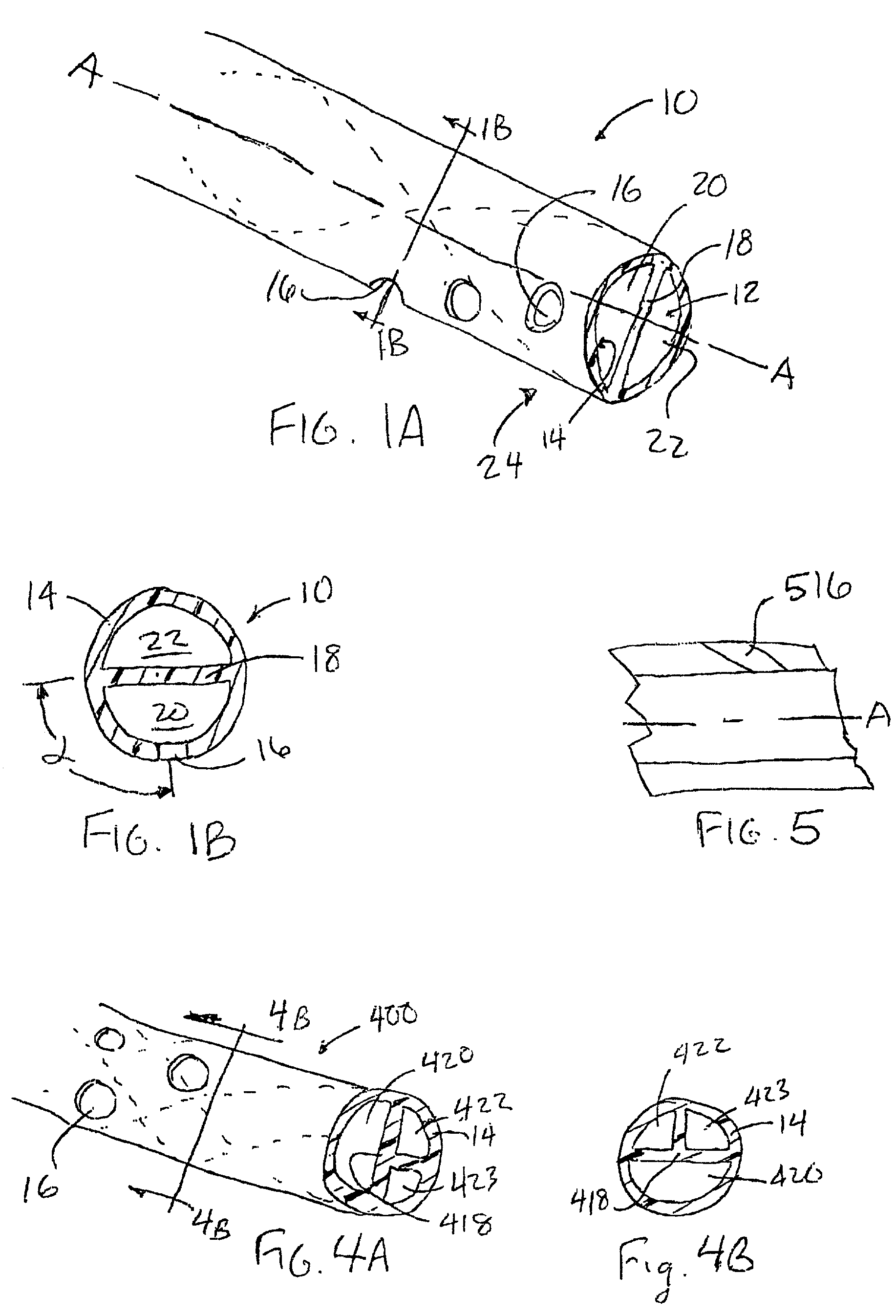
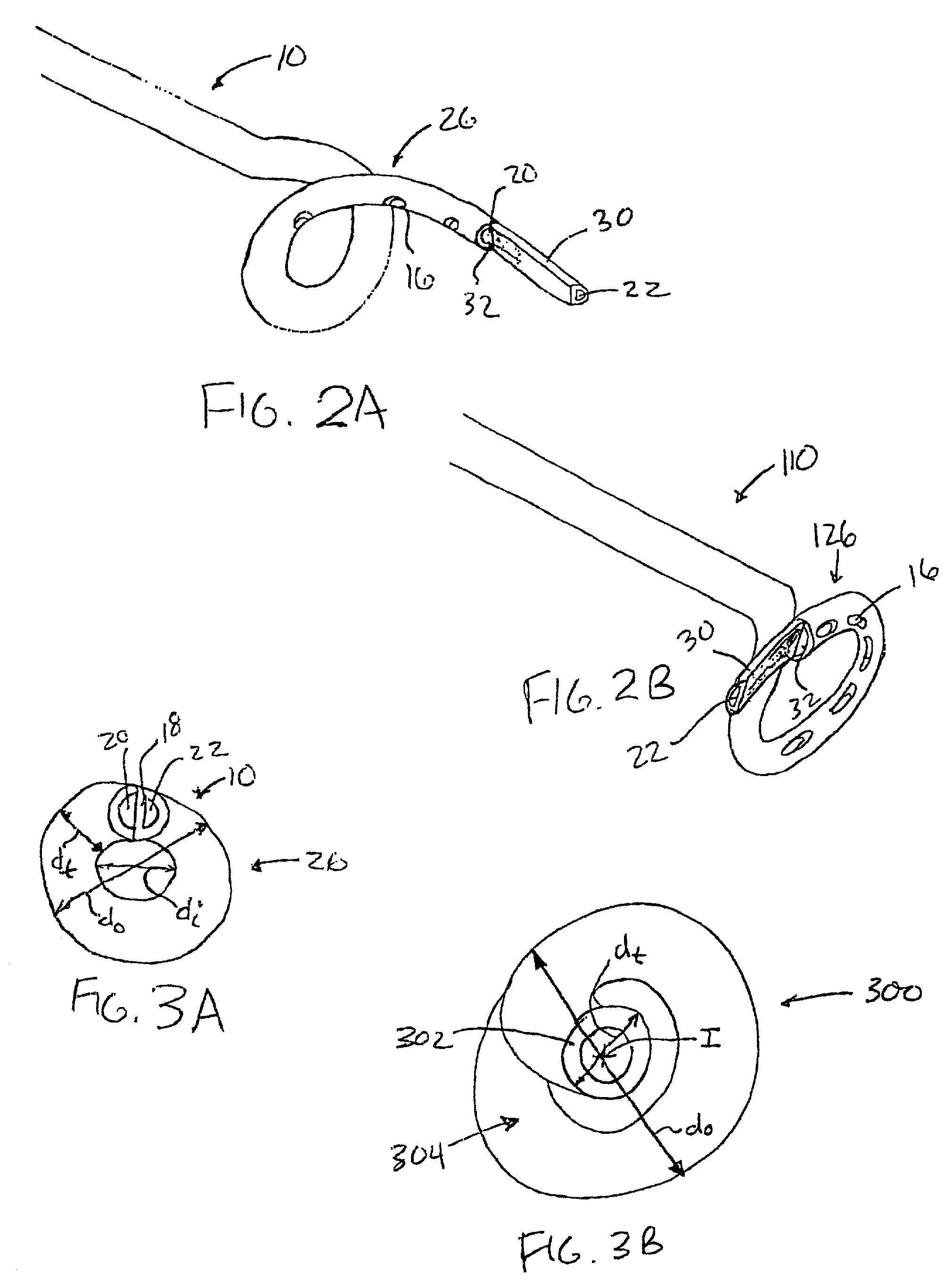
[0025]Referring now to FIGS. 1A-5, there are shown several embodiments of the invention. As shown in FIGS. 1A and 1B, catheter 10 comprises an elongated tube having an interior 12 defined by a sidewall 14 having a plurality of openings 16 formed in the sidewall, and a septum 18. Septum 18 divides interior 12 into a first lumen 20 and a second lumen 22. As shown by the dashed lines in FIG. 1A, the first lumen and second lumen form a double helix about one another as septum 18 twists about the common axis A of the catheter, as further illustrated by the cross section of FIG. 1B. FIG. 1B, a cross-section of catheter 10 taken a predetermined distance from the end 24 of the catheter show...


PUM

PropertyMeasurementUnit
Lengthaaaaaaaaaa
Luminous fluxaaaaaaaaaa
Angleaaaaaaaaaa

Abstract

A catheter comprises an elongated tube having an interior defined by a sidewall having openings. At least a portion of the catheter is spirally formed into a corkscrew pattern or has an inwardly spiraling portion with at least one opening coincident therewith. Additionally or alternatively, the catheter comprises a septum that divides the interior into at least first and second lumens. The first and second lumens may form a double helix in a portion of the catheter coincident with the plurality of openings or along the entire length of the catheter. Methods of manufacturing the catheters involve extruding the portion of the catheter having the openings, making this portion separately then attaching it to another catheter, or heating and deforming a portion of a catheter to form a tip portion. The catheter can be used for hemodialysis by drawing blood through one lumen and returning it through another.

Description

TECHNICAL FIELD[0001]This invention relates generally to perfusion catheters and, more specifically, to a catheter that is resistant to occlusion of its sidewall openings.BACKGROUND OF THE INVENTION[0002]Perfusion catheters used for introducing or removing fluids from a body lumen are well known in the art. Such catheters may be used in drug therapy, such as chemotherapy, where the fluid to be introduced is a pharmaceutical agent. Perfusion catheters have also been used to allow for bypassing occlusions in blood vessels. For example, during angioplasty, plaque may become partially or completely dislodged and may form a restriction that at least partially occludes an arterial passage. A perfusion catheter may be positioned in the occluded blood vessel across the restriction, such as is described in U.S. Pat. No. 4,661,094, incorporated herein by reference, to allow blood to flow into the catheter through a first opening upstream of the restriction and flow out through a second openin...

Claims


Application Information

Patent Timeline
IPC IPC(8): A61M37/00A61M25/00A61M3/00A61M25/14
CPCA61M25/0023A61M25/003A61M25/0043Y10T156/10A61M25/007A61M2025/0031A61M2025/004A61M25/005
Inventor HEATH, KEVIN R.BERRY, MICHELLE M.
Owner NAVILYST MEDICAL
Learn More