Liquid conductive cooling/heating device and method of use

a cooling/heating device and liquid conductive technology, applied in the field of liquid conductive cooling/heating devices and methods of use, can solve the problems of fluids passing through the flexible tubing in the grooves that may lose or gain temperature, and do not use electricity for heating or cooling medical fluids, so as to promote the warming of medical fluids and increase the rate of heating the medical fluids

a cooling/heating device and liquid conductive technology, applied in the field of liquid conductive cooling/heating devices and methods of use, can solve the problems of fluids passing through the flexible tubing in the grooves that may lose or gain temperature, and do not use electricity for heating or cooling medical fluids, so as to promote the warming of medical fluids and increase the rate of heating the medical fluids

US7276046B1Inactive Publication Date: 2007-10-02LCR HALLCREST

Image

  • Liquid conductive cooling/heating device and method of use
  • Liquid conductive cooling/heating device and method of use
  • Liquid conductive cooling/heating device and method of use

Examples


Embodiment Construction

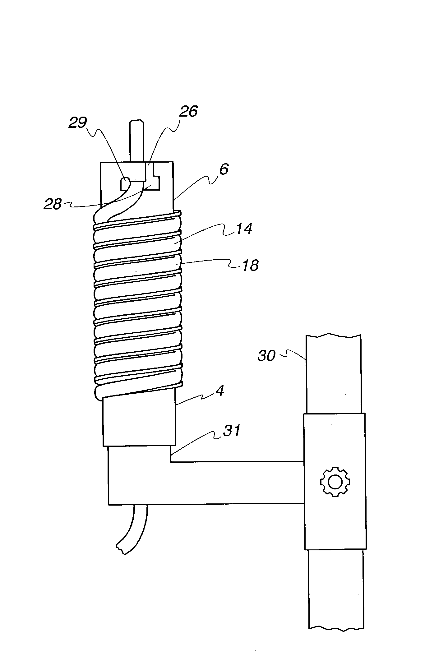
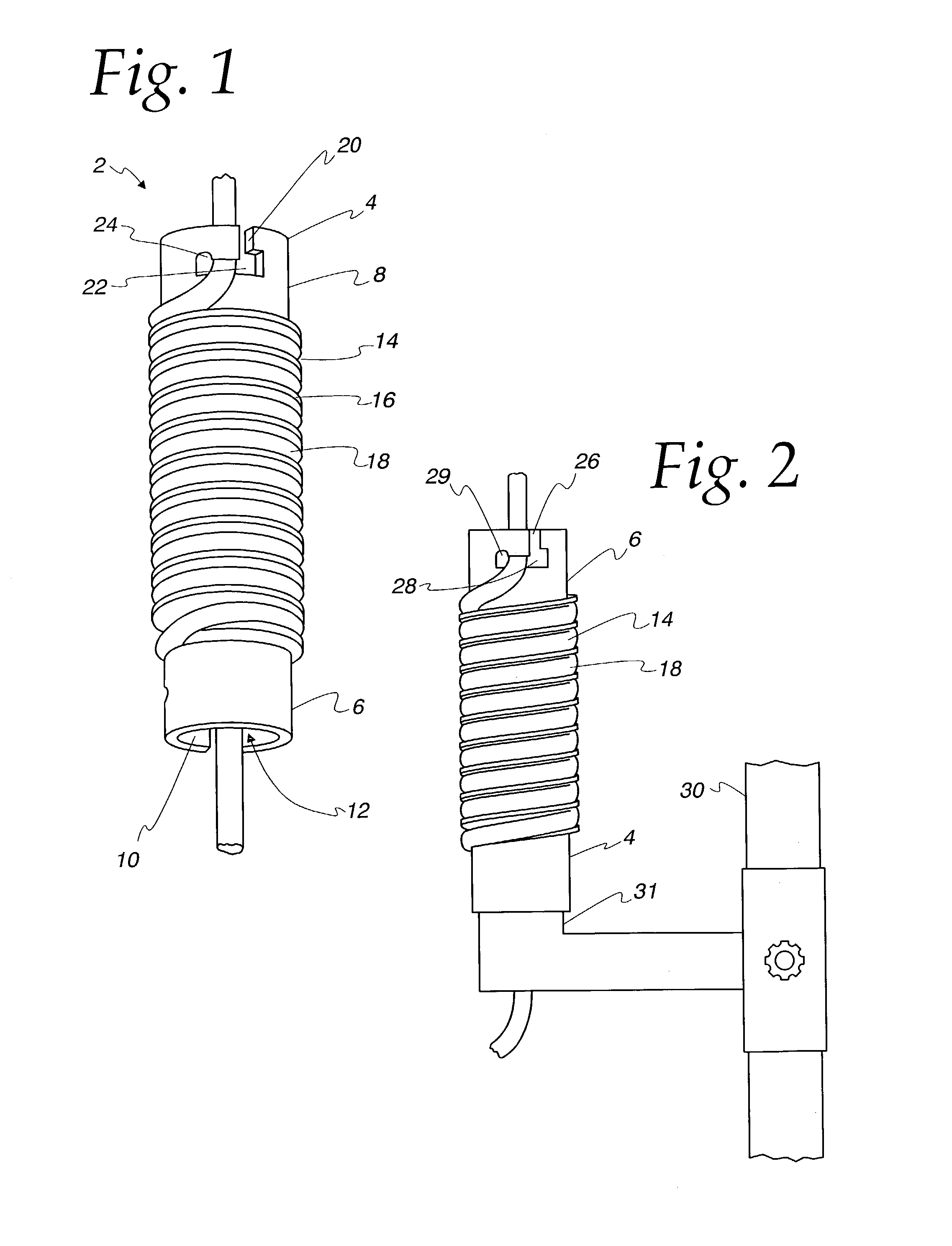
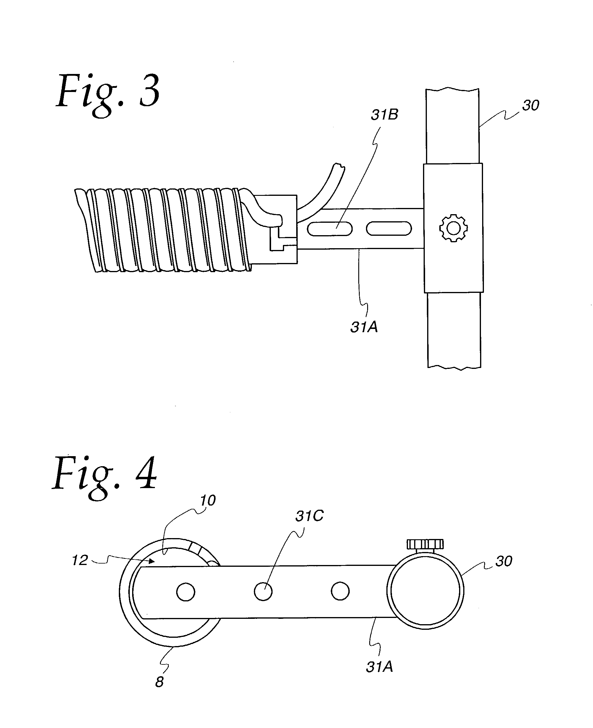
[0032]With reference to FIG. 1, a heat / cold exchanging device 2 in accordance with the invention is shown having a first end 4 and an opposite or second end 6. The distance between the first end 4 and second end 6 is preferably about 1.78 cm so that the compact device can fit on the palm of a hand. The small size renders the device convenient for use. The heat / cold exchange device is cylindrically shaped with an outside wall 8 and inside wall 10 defining a hollow space 12. Preferably, the diameter inside of the cylindrically shaped inside wall 10 is about 0.49 cm. Grooves 14 are formed on the surface of outside wall 8. The grooves 14 are defined or separated from each other by walls 16. The grooves may be of any suitable width for holding a flexible tubing 18, the width being dependent on the width of the tubing. Typically, plastic flexible tubing used in the present invention will have an outside diameter of about 3 / 16 inch with an inside diameter of about â…› inch. The grooves 14 ru...


PUM


Abstract

A device for heating or cooling medical fluids to be administered to a patient is disclosed. The device comprises a hollow, cylindrical heat / cold exchanging body having external grooves for receiving flexible tubing, the body comprising conductive material for transferring heat or cold from the medical fluid flowing to the patient. A method of using the device is also disclosed.

Description

BACKGROUND OF THE INVENTION[0001]This invention relates to a device for moderating the temperature of physiological or medical fluids. More particularly, this invention relates to the transfer bio-conduction of cold or hot energy from blood or other fluids before the blood or fluids are infused into a patient.[0002]It is established that rapid infusion of cold blood and other cold fluids may cause a recipient's heart to stop. Complications caused by rapid infusion of cold blood or other fluids may be prevented by allowing the blood or fluid to warm as it passes through the delivery tubing on its way to the patient.[0003]Rapid infusion of large amounts of fluid, plasma or blood, that are stored at low temperatures, approximately 4° C., can result in hypothermia. Patients at the greatest risk of infusible materials are the elderly, severely traumatized or with prolonged hypotension. Those who are undergoing open-heart surgery or abdominal surgery also suffer heat loss. The adverse eff...

Claims


Application Information

Patent Timeline
02 Oct 2007
Publication
US7276046B1
IPC
A61F7/12
CPC
A61M5/44; A61M5/1418; A61M2205/3606
Inventors
SUZUKI, FRED K.; MEAD, LAWRENCE C.