Tower for a wind power station

a technology for wind power stations and towers, which is applied in the direction of mechanical equipment, machines/engines, electric generator control, etc., can solve the problems of entanglement of the tower base, the difficulty of transporting towers of diameters larger than 4.3 m, and the critical engineering limitation of the required tower diameter at the tower bas

Active Publication Date: 2007-10-02
SIEMENS GAMESA RENEWABLE ENERGY SERVICE GMBH
View PDF16 Cites 44 Cited by
  • Summary
  • Abstract
  • Description
  • Claims
  • Application Information

AI Technical Summary

Benefits of technology

[0007]The objective of the present invention is to design a tower for large wind-driven power-plants in a manner to eliminate the drawbacks of the state of the art, in particular regarding transportability, economics, maintenance and blade clearance.

Problems solved by technology

Regarding large wind-driven power-plants having rotor diameters of more than 70 m and towers of heights in excess of 80 m, their output power being more than 1.5 megawatt, the critical engineering limitation is the required tower diameter at the tower base.
Towers of diameters larger than 4.3 m can be transported only with difficulty because frequently the clearance underneath bridges would not allow going through the underpass.
In addition to transportation costs, such large annular flange connection means entail considerable costs when very large wind-driven power-plants (3-5 Mw) are involved.
Both types of towers however entail higher manufacturing costs than tubular steel towers.
However the transition zone between steel tower and concrete tower entails complex engineering and high costs.
Besides the advantage of problem-free transportation, such towers however also have the critical drawback of a much larger horizontal expanse than a comparable steel tube or concrete tower, frequently raising the problem of the required safe distance between the rotor blade tip and the tower (blade clearance).
If in the event of a storm, if the rotor blade were to be excessively bent out of shape, there would be danger of contact with the tower and dire consequences for the entire edifice.
Illustratively, the dynamically highly stressed towers of the wind-driven power-plants must be checked periodically, and such maintenance at the lofty heights of the lattice towers is dangerous, time-consuming, physically exhaustive and must be carried out by highly skilled specialists.
Such designs suffer from the drawbacks of requiring very demanding engineering work at the transition zone between the shell construction (tubular tower) and the framework construction (lattice tower).
Farther below, where the tower is primarily loaded by the rotor thrust bending torque generated by the leverage of the tower length, such a design becomes uneconomical.

Method used


Image

  • Tower for a wind power station
  • Tower for a wind power station
  • Tower for a wind power station

Examples


Embodiment Construction

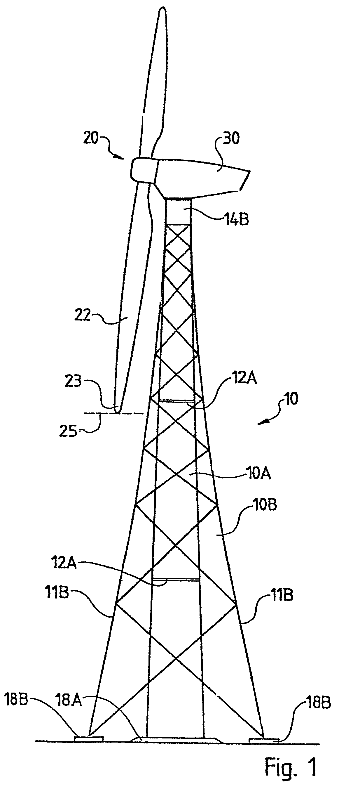
[0070]FIG. 1 shows a wind-driven power-plant of the state of the art where the supporting tower 10 is made up of two superposed tower variations, namely a tubular tower 10A and a lattice tower 10B. The tower 10 bears an equipment nacelle 30 which is rotatable about the vertical tower axis and which supports a rotor 20 bearing at least one rotor blade 22 having a blade tip 23 and being rotatable about a substantially horizontal axis. This view shows a three-blade rotor, the horizontal plane of the rotor blade tip 23 in its lowermost position being denoted by a dashed line 25.

[0071]Besides the rotor bearing, the equipment nacelle 30 conventionally also contains a generator, a gear unit where called for, a wind tracking system, various electric components and further accessory systems. Such parts are omitted for the sake of clarity.

[0072]Because of transportation, the tubular tower 10A is fitted with several flange connections 12A. In the state of the art, these flange connections are ...


PUM


Abstract

Disclosed is a tower for a wind power station comprising a machine pod disposed on the tower and a rotor mounted on the machine pod so as to be rotatable about an essentially horizontal axis. Said rotor is provided with at least one blade. The tower is composed of a tubular upper section that is connected to a lower section which is embodied as a lattice tower in a transition zone. The lattice tower encompasses at least three corner posts. The upper tower section forms at least one sixth of the entire tower. The cross section of the lower tower section below the transition zone is greater than the cross section of the upper tower section while the transition zone is configured such that the cross section of the lower tower section is adjusted to the cross section of the upper tower section so as to optimize power flux.

Description

BACKGROUND OF THE INVENTION[0001]Modem wind-driven power-plants are predominantly designed to rest on tubular towers, in particular steel tube towers, because this design, termed shell design, is the simplest and most economical. Regarding large wind-driven power-plants having rotor diameters of more than 70 m and towers of heights in excess of 80 m, their output power being more than 1.5 megawatt, the critical engineering limitation is the required tower diameter at the tower base. Towers of diameters larger than 4.3 m can be transported only with difficulty because frequently the clearance underneath bridges would not allow going through the underpass. Moreover the total length and weight of such towers demands subdividing them into several tower sections that are bolted to each other by annular flanges. In addition to transportation costs, such large annular flange connection means entail considerable costs when very large wind-driven power-plants (3-5 Mw) are involved.[0002]In v...

Claims


Application Information

Patent Timeline
Patent Type & Authority Patents(United States)
IPC IPC(8): F03D11/04
CPCE02D27/42F03D11/04E02B17/027E04H2012/006F05B2240/40E02B2017/0091F05B2240/9121Y02E10/728E02B2017/006F05B2240/912F03D13/20E02D27/425F03D9/255F03D80/85Y02E10/72
Inventor WEITKAMP, ROLANDHINZ, UWESCHAFER, STEPHAN
Owner SIEMENS GAMESA RENEWABLE ENERGY SERVICE GMBH
Why Eureka
Try Eureka