Vertical alignment mode LCD with larger dielectric protrusions in transmissive region than in reflection region

a vertical alignment and dielectric protrusion technology, applied in non-linear optics, instruments, optics, etc., can solve the problems of difficult control of the height of these projections, inability to control the direction of liquid crystal molecules' tilt, and large difference in distance between the substrates of the liquid crystal display devi

Active Publication Date: 2007-10-02
BOE TECH GRP CO LTD
View PDF27 Cites 17 Cited by
  • Summary
  • Abstract
  • Description
  • Claims
  • Application Information

AI Technical Summary

Benefits of technology

[0013]The object of the invention is to provide a liquid crystal display device enabling display with a wide viewing angle by solving the above-mentioned problems by providing a transreflective liquid crystal display device using homeotropic liquid crystal in which the direction of tilt of the liquid crystal molecules can be controlled easily and accurately. Another object of the invention is to provide a simply-structured transreflective liquid crystal display device using homeotropic liquid crystal. In this way, the manufacturing efficiency of the liquid crystal display device is improved and the reliability is increased in that the number of possible defects is reduced. Another object of the invention is to provide a highly reliable electronic apparatus including the liquid crystal display device.
[0025]The second protrusions are preferably formed in a same process as the above-mentioned protrusions (which are hereinafter referred to as the first protrusions) for controlling the direction of tilt of the liquid crystal molecules in order to improve the production efficiency. In this case, the first and the second protrusions formed in the transmissive display area and / or the reflective display area are composed of the same material. Moreover, the second protrusions have a substantially identical height as the first protrusions formed in the transmissive display area and / or the reflective display area. Since the first and the second protrusions in the transmissive display area and / or the reflective display area have a substantially identical height, the first protrusions are prevented from contacting the opposing substrate. Thus, the alignment of the liquid crystal molecules is sufficiently controlled.

Problems solved by technology

However, a great difference is created in the distance between the substrates of a liquid crystal display device having a multi-gap structure and having projections for controlling the direction of tilt of the liquid crystal molecules.
This is a problem because it is difficult to form projections on the substrates where the distance between the substrates differ and it is difficult to control the height of these projections.
Not being able to form the projections with a predetermined height may cause a problem in that the direction of tilt of liquid crystal molecules cannot be controlled.

Method used


Image

  • Vertical alignment mode LCD with larger dielectric protrusions in transmissive region than in reflection region
  • Vertical alignment mode LCD with larger dielectric protrusions in transmissive region than in reflection region
  • Vertical alignment mode LCD with larger dielectric protrusions in transmissive region than in reflection region

Examples


second embodiment

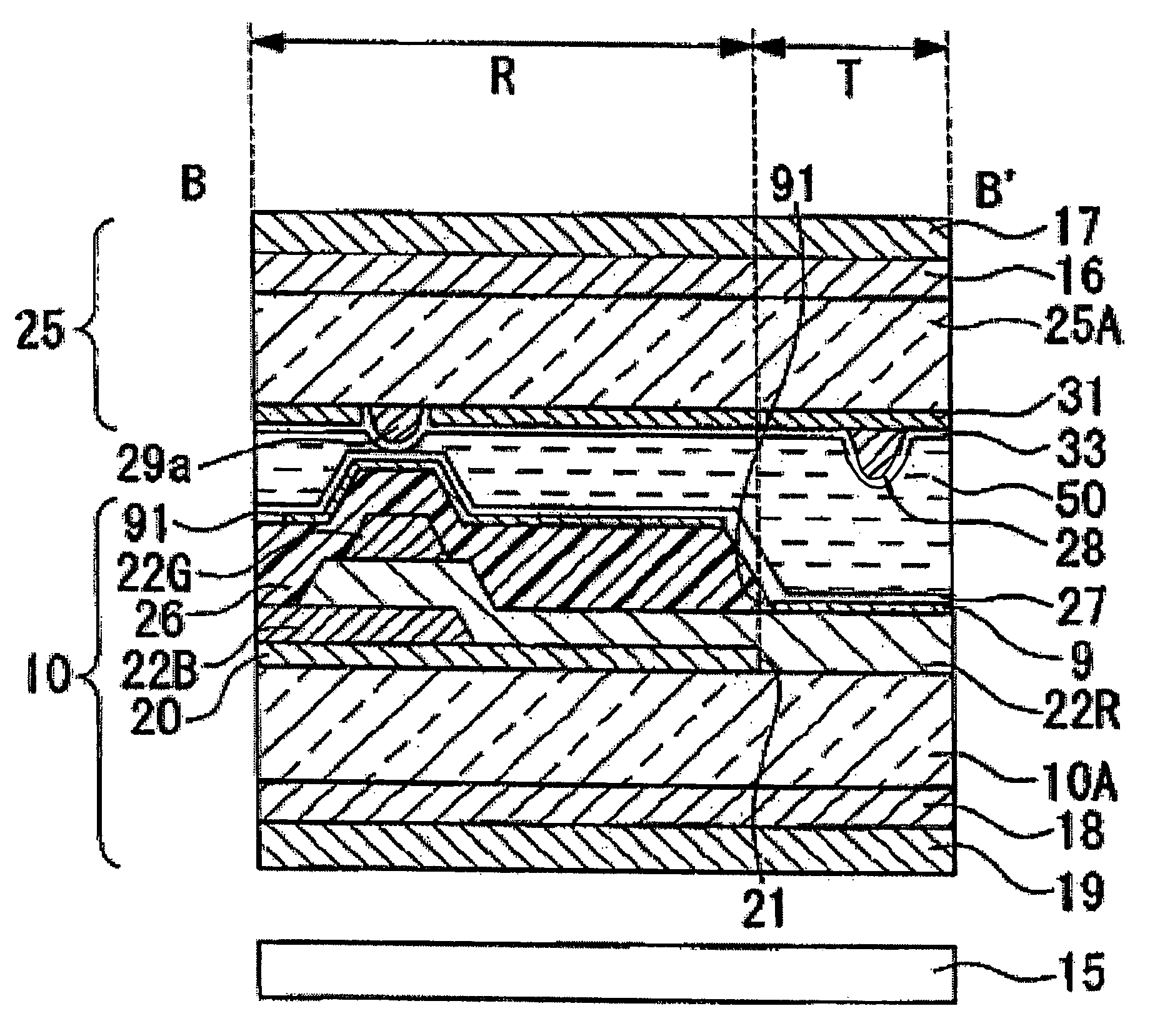
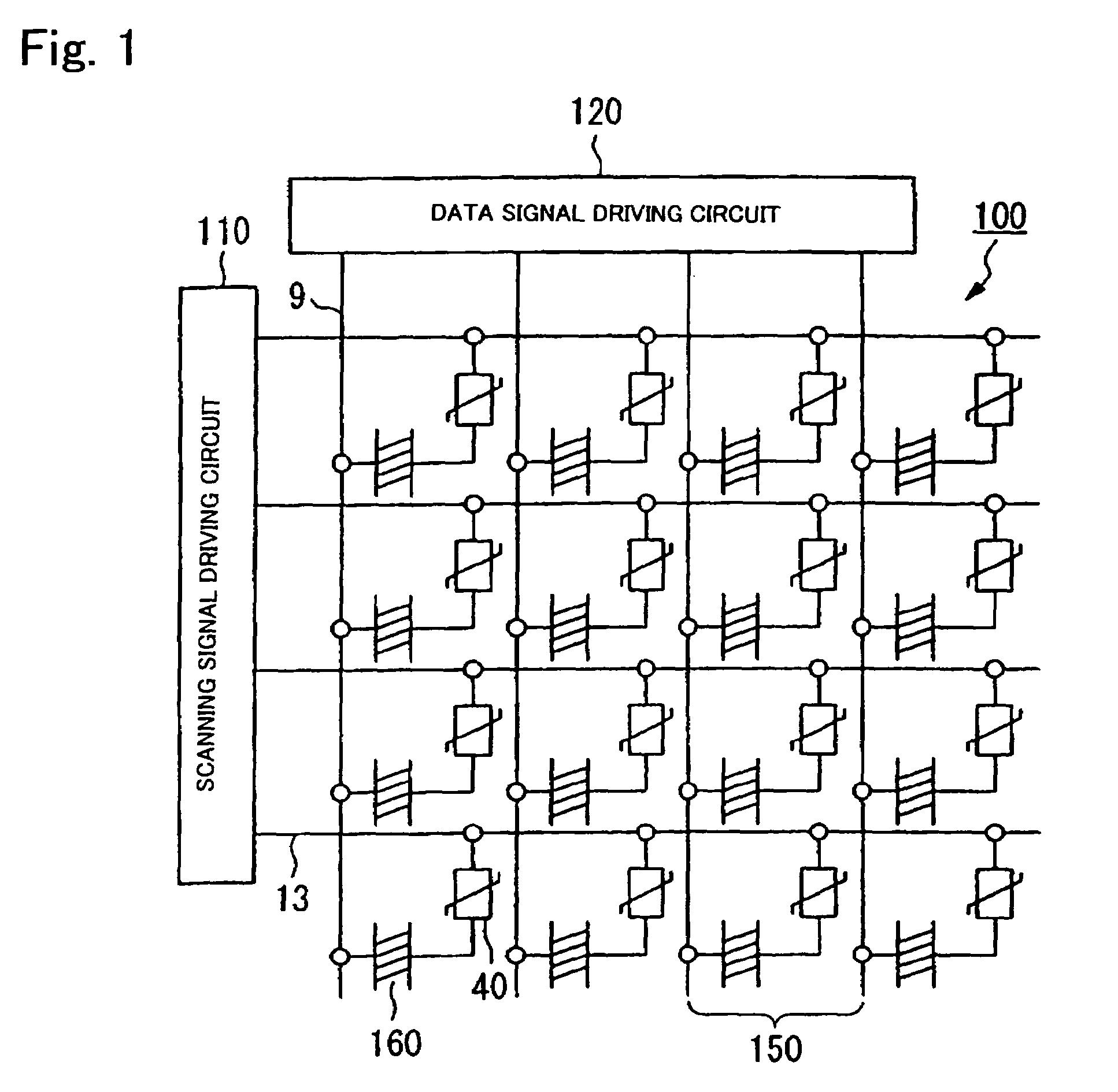
[0069]The liquid crystal display device 200 is an active matrix transreflective liquid crystal display device including a TFD as a switching element. The liquid crystal display device 200 includes a liquid crystal layer 50 interposed between an upper substrate (element substrate) 25 and a lower substrate (opposing substrate) 10. The liquid crystal layer 50 is composed of a liquid crystal having molecules that are vertically aligned at an initial alignment state and have negative dielectric anisotropy.

first embodiment

[0070]A part of the lower substrate 10 includes a substrate body 10A composed of a transparent material, such as quartz or glass, and a reflective film 20 composed of a metal, such as aluminum and silver, with a high reflectance. The reflective film 20 is formed in a predetermined pattern or, in other words, formed selectively on a reflective display area R. The lower substrate 10 also has a bumpy surface similar to the structure of the first embodiment formed of an insulating film 24 interposed between the substrate body and the reflective film.

[0071]On the reflective film 20 selectively formed on the reflective display area R and on the substrate body 10A of the transmissive display area T, a color filter 22 (22R, 22G, and 22B) is disposed across the reflective display area R and the transmissive display area T. The color filter 22 includes color layers 22R, 22G, and 22B that are red, green, and blue, respectively. The color layers 22R, 22G, and 22B make up dot areas D1, D2, and D...

third embodiment

[0079]As shown in FIG. 6, the liquid crystal display device 400 is an active matrix transreflective liquid crystal display device including a thin-film transistor (TFT) as a switching element. The liquid crystal display device 400 includes a liquid crystal layer 50 interposed between a lower substrate (element substrate) 10 and an upper substrate (opposing substrate) 25. The liquid crystal layer 50 is composed of a liquid crystal having molecules that are vertically aligned at an initial alignment state and have negative dielectric anisotropy.

[0080]A part of the lower substrate 10 includes a substrate body 10A and a reflective film 20a composed of a metal, such as aluminum or silver, with a high reflectance on the substrate body 10A. The reflective film 20a is formed in a predetermined pattern or, in other words, formed selectively on a reflective display area R. In the area without the reflective film 20a, i.e., a transmissive display area T, transparent electrodes 9a are formed w...


PUM

PropertyMeasurementUnit
thicknessaaaaaaaaaa
thicknessaaaaaaaaaa
areaaaaaaaaaaa

Abstract

The invention provides a liquid crystal display device having a wide viewing angle for transmissive display and reflective display. The liquid crystal display device according to the invention can include a homeotropic liquid crystal layer interposed between a pair of substrates. The liquid crystal display device has a transmissive display area and a reflective display area in each dot area. A liquid crystal layer thickness-adjustment layer can be interposed between at least the substrate of the pair of substrates and the liquid crystal layer. The liquid crystal layer thickness-adjustment layer reduces the liquid crystal layer thickness of the reflective display area in comparison with the liquid crystal layer thickness of the transmissive display area. On the substrate opposing the substrate with the liquid crystal layer thickness-adjustment layer, protrusions protruding from the inner surface of the substrate to the liquid crystal layer are formed.

Description

BACKGROUND OF THE INVENTION[0001]1. Field of Invention[0002]The present invention relates to a liquid crystal device and an electronic apparatus. More specifically, the invention relates to a technology for obtaining a wider viewing angle for the liquid crystal display device using homeotropic liquid crystal.[0003]2. Description of Related Art[0004]A liquid crystal device having a reflective mode and a transmissive mode is known as a transreflective liquid crystal device. Such a transreflective liquid crystal device has a liquid crystal layer interposed between an upper substrate and a lower substrate. A reflective film having a window for transmitting light through the film, composed of a metal plate, e.g., an aluminum plate, is disposed on the inner surface of the lower substrate. The reflective film functions as a transreflective plate. In such a case, in the reflective mode, the light entering from the upper substrate is transmitted through the liquid crystal layer and, then, is...

Claims


Application Information

Patent Timeline
Patent Type & Authority Patents(United States)
IPC IPC(8): G02F1/1337G02F1/1333G02F1/1335G02F1/139
CPCG02F1/133555G02F1/133371G02F1/1393G02F1/133707G02F1/1335
Inventor MAEDA, TSUYOSHI
Owner BOE TECH GRP CO LTD
Why Eureka
Try Eureka