
Contactor draw out tray

a contactor and tray technology, applied in the direction of coupling device connection, electrical apparatus construction details, engagement/disengagement of coupling parts, etc., can solve the problems of difficult repair and maintenance of equipment, difficult task for longwall power centers, and inability to evacuate defective equipment to the surface, so as to achieve the effect of easy repair

Active Publication Date: 2007-10-02
ELECTRO MECHANICAL CORP
View PDF7 Cites 14 Cited by
  • Summary
  • Abstract
  • Description
  • Claims
  • Application Information

AI Technical Summary

Benefits of technology

[0007]The movable frame is configured in a tray like manner to carry the electrical conducting and controlling components of the apparatus, such that repairs may be easily made by substitution of a defective tray with an operational tray. The defective tray may then be evacuated to a suitable repair site to return it to an operational condition.

Problems solved by technology

In electrical supply and power distribution systems and more particularly to underground mining applications utilizing the same, the repair of power distribution centers, such as longwall power centers and longwall starters is presently a difficult task.
Due to the rugged and demanding environments where this equipment is normally employed, the industry has traditionally relied upon solid bolted type or hardwired connections for the operative components and circuitry in these systems.
These same environmental considerations make repair and maintenance of the equipment a difficult task.
Due to the extensive size of such equipment, it is impractical to evacuate defective equipment to the surface in order to provide a clean environment for the technician to effectuate the necessary repairs.
In such conditions and as a consequence of such bolted connections, repairs remain a time consuming, labor intensive proposition.
Similarly, because the equipment remains in an inoperable condition for an extended period of time, there is a concomitant loss in productivity as the equipment reliant on the electrical power is rendered useless.
While there have been efforts in the industry to modularize critical components in these systems to improve the maintainability of the systems, their use remains limited.

Method used


Image

  • Contactor draw out tray
  • Contactor draw out tray
  • Contactor draw out tray

Examples


Embodiment Construction

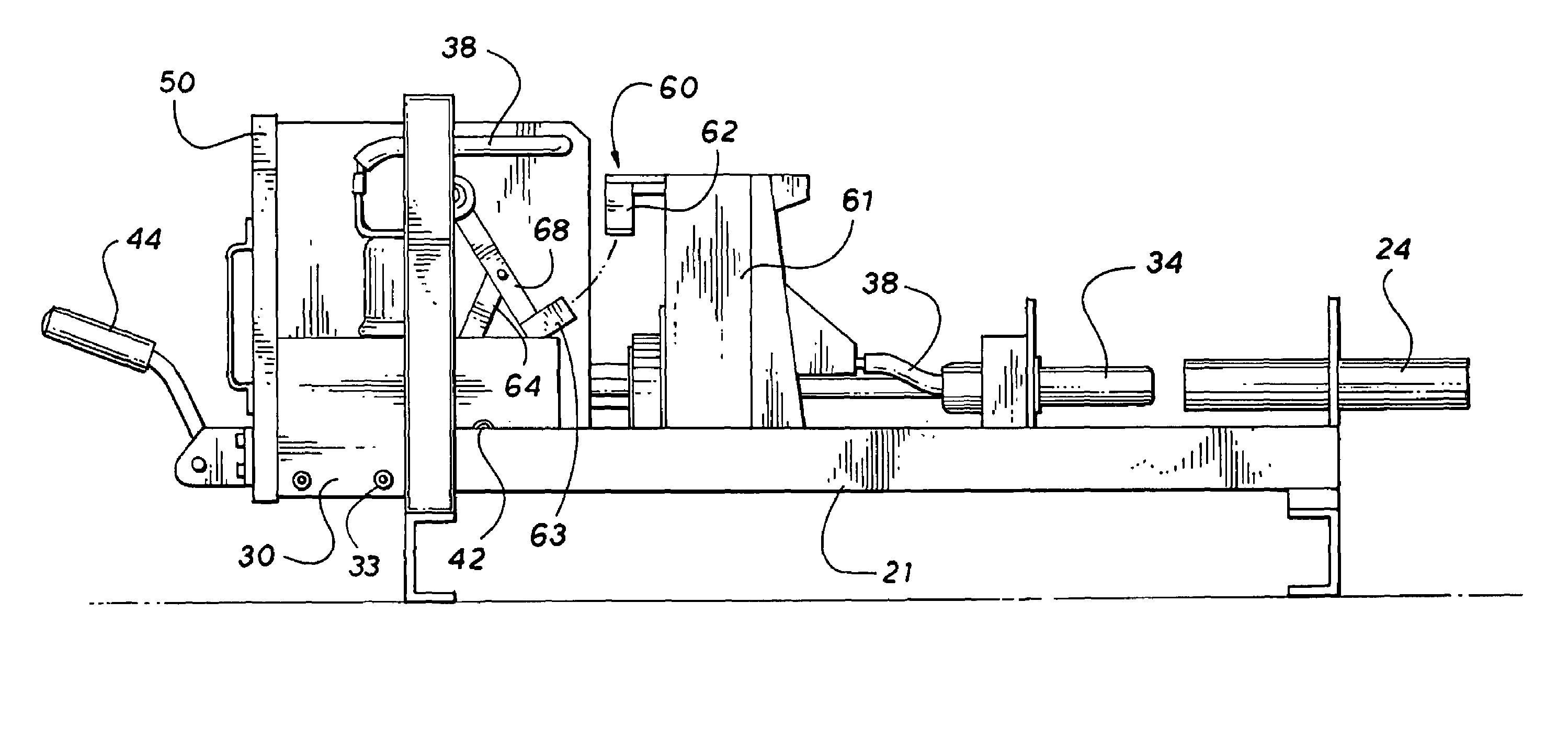
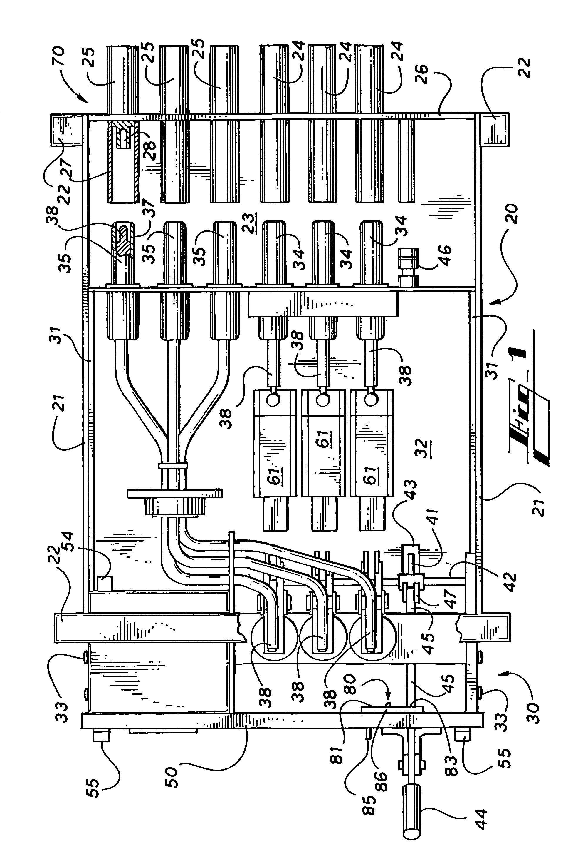
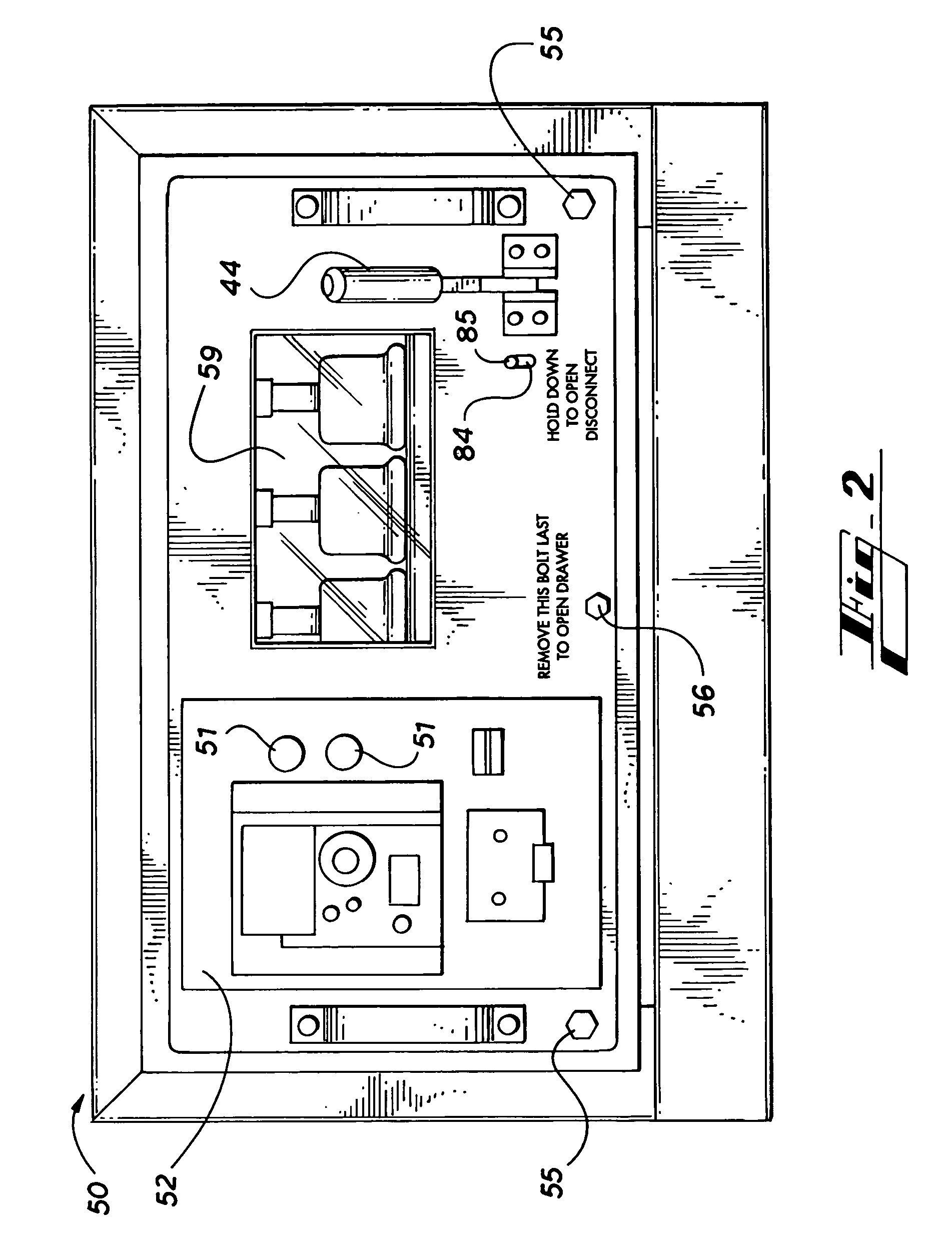
[0018]Referring to the drawings for a fuller understanding of the invention, FIG. 1 shows an exemplary embodiment of an electrical contactor tray of the present invention. The contactor tray comprises a stationary frame 20, a movable frame 30, a front panel 50, and a rear panel 70.

[0019]Stationary frame 20 generally comprises a pair of longitudinal support rails 21, end supports 22, and a base plate 23 for supporting the electrical components carried by the stationary frame 20. Preferably base plate 23 will extend between support rails 21 and end supports 22 to prevent the infiltration of dust, moisture and other contaminants from beneath the apparatus which might adversely effect the longevity and performance of the electrical components.

[0020]Stationary frame 20 may further comprise a suitable enclosure (not shown) to protect the electrical components from the aforementioned environmental hazards, such that the apparatus may be utilized in a stand alone configuration. More prefera...


PUM


Abstract

An electrical contactor draw out tray has a movable frame and a stationary frame in which the movable frame carries the electrical components for an electrical feeder circuit. The stationary frame is preferably housed within a power distribution center and has input terminals for the incoming electrical power and output terminals for delivering electrical power to equipment operating on the feeder circuit. The movable frame carries the contactors that control the flow of electricity through the apparatus as well as the electrical components to monitor conditions of the apparatus and various parameters for the electricity carried therein to for conditions such as short circuits, overloads, ground faults, overvoltages and undervoltages. A disconnect mechanism locks the movable frame relative the stationary frame and provides a primary means for disengaging electrical flow through the apparatus.

Description

FIELD OF THE INVENTION[0001]The present invention relates to the field of electrical supply systems, and more particularly to the field of electrical feeder circuits. With even greater particularity, the invention relates to a modularized feeder circuit control panel for a power distribution center for underground mining activities.BACKGROUND OF THE INVENTION[0002]In electrical supply and power distribution systems and more particularly to underground mining applications utilizing the same, the repair of power distribution centers, such as longwall power centers and longwall starters is presently a difficult task. Due to the rugged and demanding environments where this equipment is normally employed, the industry has traditionally relied upon solid bolted type or hardwired connections for the operative components and circuitry in these systems. The underlying logic behind these methods is the desire to eliminate any potential weak point in the circuitry that may be compromised due t...

Claims


Application Information

Patent Timeline
Patent Type & Authority Patents(United States)
IPC IPC(8): H05K7/16
CPCH01R13/6335H01R13/635Y10S439/911H01R2201/04
Inventor CARLSON, KURT NELS
Owner ELECTRO MECHANICAL CORP
Learn More