Automatic gain control of multiple antenna OFDM receiver

a receiver and multiple antenna technology, applied in the field of wireless communication system, can solve the problems of 54 mbps transfer limit, prior art does not teach automatic gain control in a receiver having multiple antennas and corresponding data paths

Active Publication Date: 2007-10-02
REALTEK SEMICON CORP
View PDF18 Cites 37 Cited by
  • Summary
  • Abstract
  • Description
  • Claims
  • Application Information

AI Technical Summary

Benefits of technology

[0014]It is an advantage of the claimed invention that the candidate power is determined according to the RMS power of the first group of symbols.
[0015]It is a further advantage of the claimed invention that the candidate power can be further determined according to a plurality of methods, with the most suitable candidate power being used to set the gain of the amplifier.

Problems solved by technology

This 54 Mbps transfer limit for WLANs is a consequence of current technological limitations and regulation, such as that according to IEEE 802.11a or 802.11g for example.
However, the prior art does not teach automatic gain control in an OFDM receiver having multiple antennas and corresponding data paths for a single frequency band.

Method used


Image

  • Automatic gain control of multiple antenna OFDM receiver
  • Automatic gain control of multiple antenna OFDM receiver
  • Automatic gain control of multiple antenna OFDM receiver

Examples


Embodiment Construction

[0029]General Configuration:

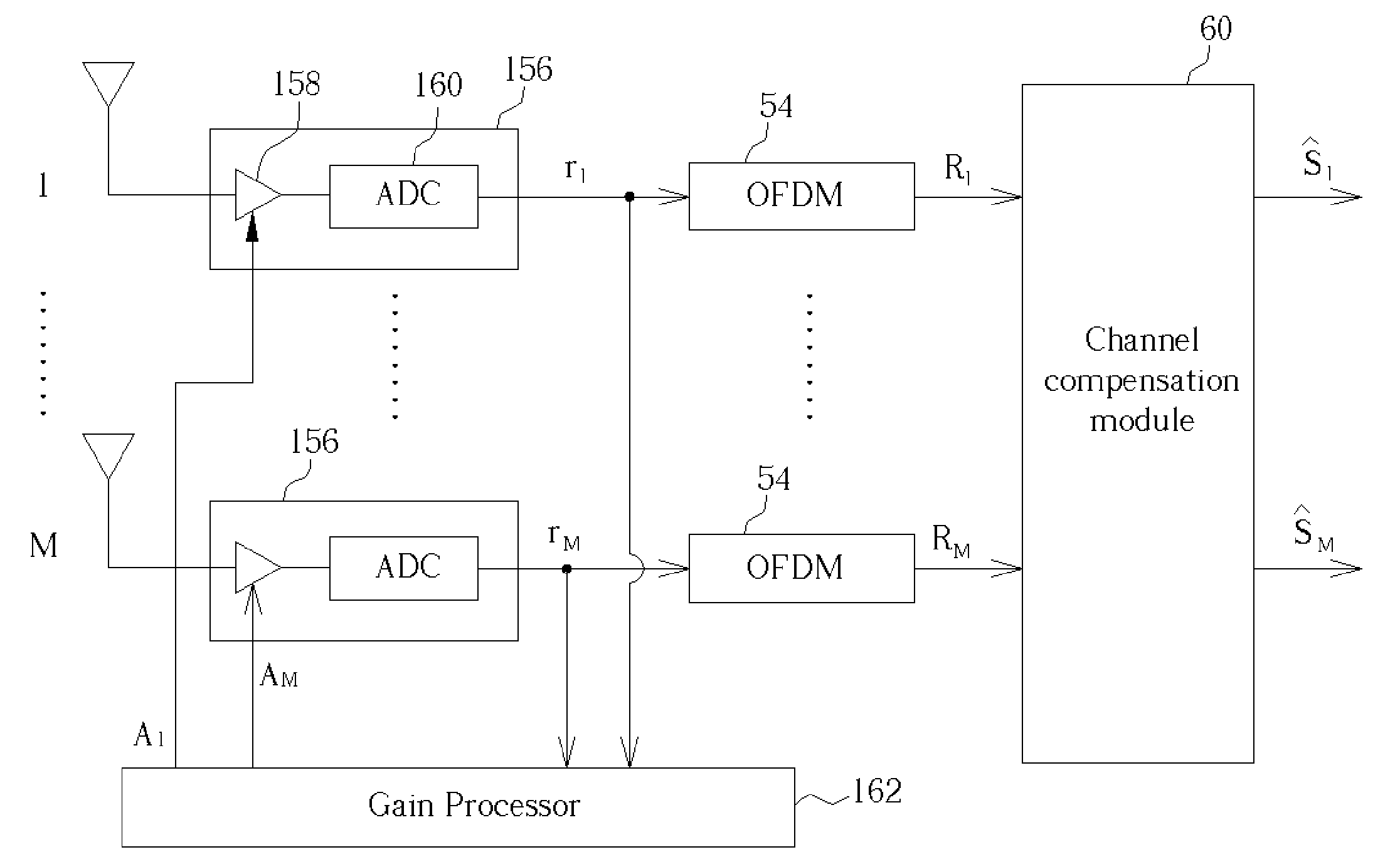
[0030]Please refer to FIG. 3, which is a schematic diagram illustrating signal transmission and reception in a multiple transmitter / receiver antenna application. When a group of signals s1-sM is transmitted along the pathways, h11 etc, shown, they are substantially simultaneously received as signals r1-rM after undergoing inter-antenna interference. Generally, for M transmitters and receivers, such transmission and interference can be described by the channel impulse response matrix as follows:

[0031]h=[h11h12⋯h1⁢Mh21h22⋯h2⁢M⋮⋮⋰⋮hM1hM2⋯hMM],(1)

where

[0032]h is a channel impulse response, and

[0033]M is a total number of antennas in the transceiver.

[0034]The digits of the index of each channel impulse response value, h, respectively indicate the receiver and transmitter antennas defining such channel. For example, the channel impulse response value h12 corresponds to the channel from a second transmitter antenna to a first receiver antenna. The channel impuls...


PUM


Abstract

A method includes amplifying the plurality of received signals, generating a plurality of time domain samples of the amplified signals with at least an analog-to-digital converter (ADC), determining at least a candidate power according to root-mean-square (RMS) powers of a first group of symbols received at the receiver antennas, and setting the gain of the amplifier according to a selected candidate power with the processor. The received RMS power for one antenna is determined as the square root of the averaged product of each received symbol and its complex conjugate for all symbols of the first group. The candidate power can be determined considering a subgroup of antennas using an RMS value, an arithmetical mean value, or a geometric mean value of this subgroup.

Description

CROSS REFERENCE TO RELATED APPLICATIONS[0001]This is a continuation-in-part of application Ser. No. 10 / 249,557, filed Apr. 17, 2003, which is included in its entirety herein by reference.BACKGROUND OF INVENTION[0002]1. Field of the Invention[0003]The present invention relates to a wireless communication system, and more specifically, to automatic gain control in a receiver of a multiple-antenna system.[0004]2. Description of the Prior Art[0005]Wireless local area networks (WLANs) are ever increasingly being used in network environments where mobility is of importance. Orthogonal frequency division multiplexing (OFDM) is a well-known concept used in implementing WLAN system. A typical WLAN employing OFDM can achieve a maximum data transfer rate of 54 Mbps per client, which is significantly less than the wire-based LAN capability of between 100 Mbps to 10 Gbps. This 54 Mbps transfer limit for WLANs is a consequence of current technological limitations and regulation, such as that acco...

Claims


Application Information

Patent Timeline
Patent Type & Authority Patents(United States)
IPC IPC(8): H04B7/00H04B17/00H04L25/02H04L27/26H04Q7/36
CPCH04L25/022H04L27/261H04L25/0242H04B17/20
Inventor LIU, DER-ZHENGYANG, SHAN-ANYEN, KUANG-YU
Owner REALTEK SEMICON CORP
Why Eureka
Try Eureka