Method of making a filter assembly having a flexible housing

a flexible housing and filter assembly technology, applied in the direction of glue vessels, cartridge filters, external supports, etc., can solve the problems of pvc material sheets, difficult to form a complete and reliable seal, and difficult to provide an efficient and reliable method for forming an inlet and an outlet port in the filter housing

Inactive Publication Date: 2007-10-09
FENWAL
View PDF102 Cites 26 Cited by
  • Summary
  • Abstract
  • Description
  • Claims
  • Application Information

AI Technical Summary

Problems solved by technology

While filter housings manufactured from flexible PVC material offer the benefit of having a flexible housing, it has been heretofore difficult to provide an efficient and reliable method for forming an inlet port and an outlet port in the filter housing.
However, it is difficult to form a complete and reliable seal at the junction of the PVC material sheets and the tubing that serves as the port.
Both an incomplete seal, as well as a weak seal can lead to fluid leaking from the filter assembly during the filtering process.
Introducing fluid into a filter housing at the seal of its panels or sheets is also less desirable when the flow characteristics of the fluid across the filter media are important (e.g. laminar flow or even flow across the filter media).
If the fluid enters the housing immediately adjacent the filter media, the bubble strength of the filter media may be quickly surpassed by increased blockage of the filter media with filtered particulate and the resulting increased pressure within the filter housing may cause the filter media to rupture or burst.
This is a very undesirable result in that it is difficult, if not impossible to immediately detect a ruptured filter membrane.
Alternatively, increased blockage of the filter media may lead to turbulent fluid flow through t

Method used


Image

  • Method of making a filter assembly having a flexible housing
  • Method of making a filter assembly having a flexible housing
  • Method of making a filter assembly having a flexible housing

Examples


Embodiment Construction

[0050]Although the disclosure hereof is detailed and exact to enable those skilled in the art to practice the invention, the physical embodiments herein disclosed merely exemplify the invention which may be embodied in other specific structure. While the preferred embodiment has been described, the details may be changed without departing from the invention, which is defined by the claims.

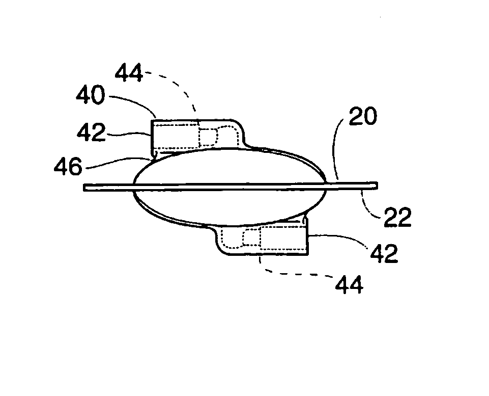
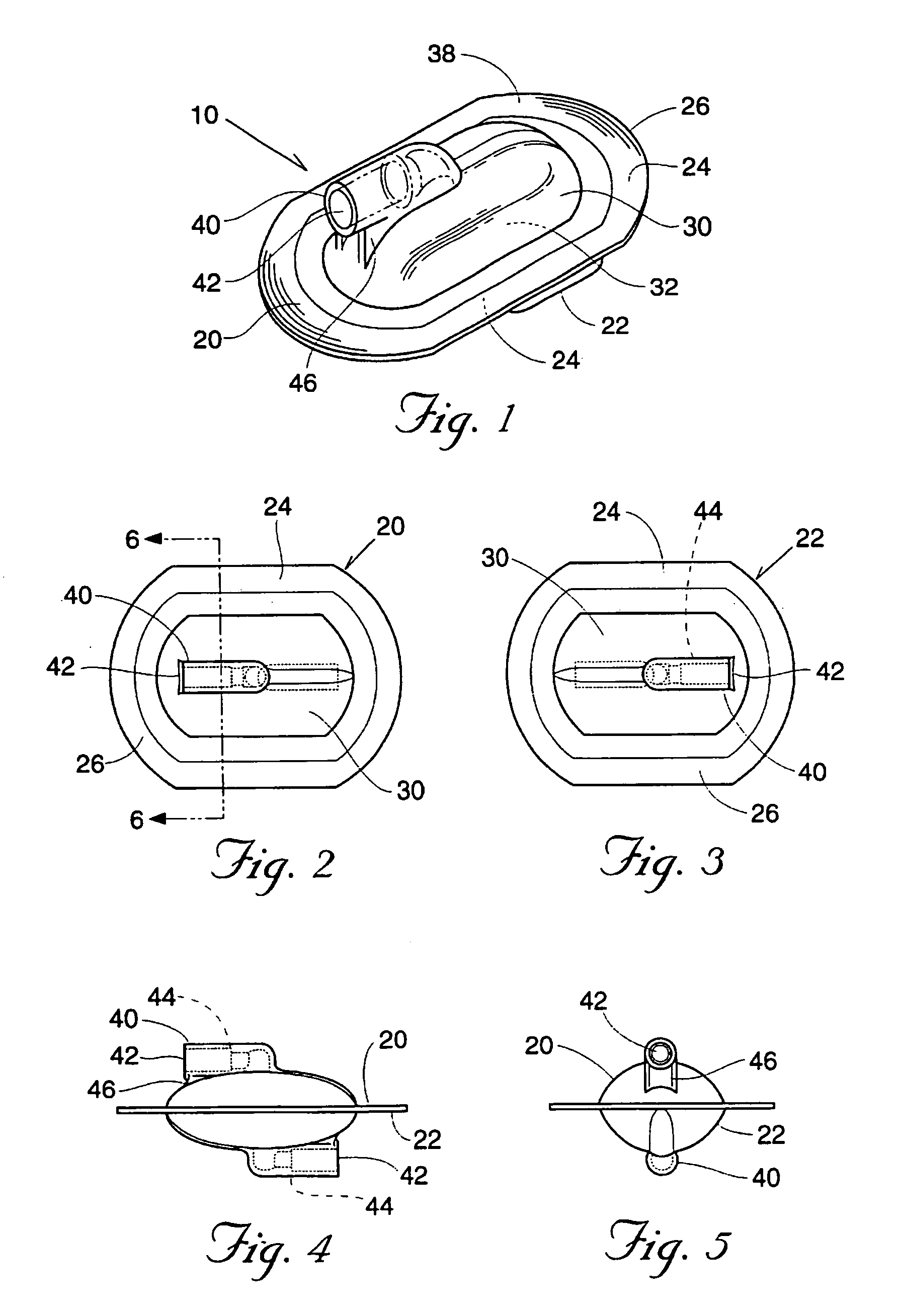
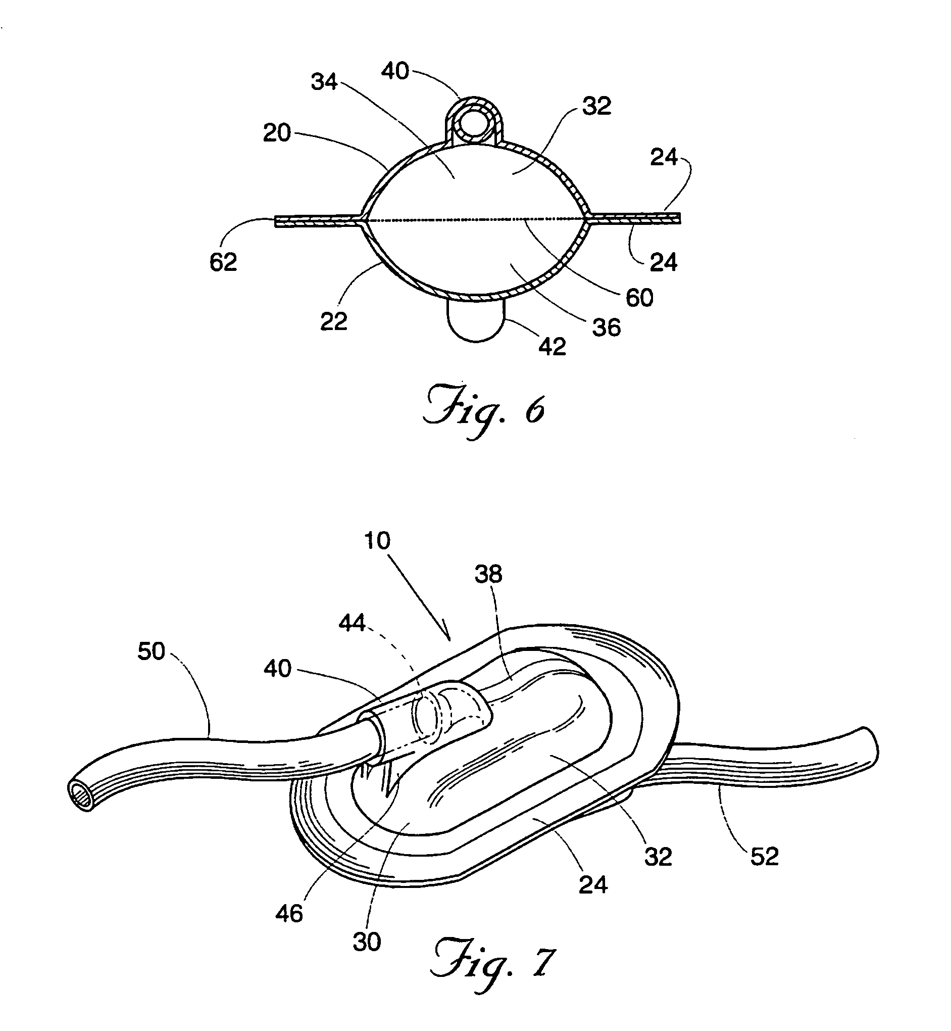
[0051]Referring more particularly to the drawings there is seen in FIG. 7 a filter assembly 10 used, for purposes of illustration only, to filter blood or blood components, e.g., red blood cells or platelet poor plasma in a manual or automated blood processing system during processing or before being returned to a donor from a blood separation apparatus. Two or more conduits, such as conduits 50 and 52 supply unfiltered blood to and convey filtered blood from the filter assembly 10 respectively. Filter media, not shown in FIG. 7, is contained within filter assembly 10. Blood filtration is only one ...


PUM

PropertyMeasurementUnit
Flexibilityaaaaaaaaaa

Abstract

A method of making a blood filter assembly provides first and second filter housing elements from a flexible thermoplastic material, each of the first and second housing elements including a molded port. The method places a filter media between the first and second filter housing elements and applies radio frequency heating and pressure to form a peripheral seal that joins the first and second filter housing elements to the filter media and encapsulates the filter media between the first and second housing elements.

Description

RELATED APPLICATIONS[0001]This application is a division of U.S. patent application Ser. No. 10 / 084,605, filed Feb. 27, 2002 (now U.S. Pat. No. 6,688,476), which is a continuation of U.S. patent application Ser. No. 10 / 055,862, filed Jan. 23, 2002 (now U.S. Pat. No. 6,601,710), which is a continuation of U.S. patent application Ser. No. 09 / 295,048, filed Apr. 20, 1999 (now abandoned), which is a continuation-in-part of U.S. patent application Ser. No. 08 / 697,270, filed Aug. 21, 1996 (now U.S. Pat. No. 6,032,807, which is a continuation of U.S. patent application Ser. No. 08 / 558,458, filed Nov. 16, 1995 (now abandoned), which is a continuation of U.S. patent application Ser. No. 08 / 392,297, filed Feb. 22, 1995 (now abandoned), which is a continuation of U.S. patent application Ser. No. 08 / 173,608, filed Dec. 22, 1993 (now abandoned).FIELD OF THE INVENTION[0002]The present invention relates to an improved filter device for filtering, entrapping air, and preventing foaming in fluids, s...

Claims


Application Information

Patent Timeline
IPC IPC(8): B01D35/00B29C65/02B29C65/04B32B37/00B32B37/06A61M1/02A61M1/36B01D29/01B01D35/02B01D35/30B01D39/08B01D39/16B01D39/18B01D39/20B29C45/00B29D99/00B29K27/06B29L22/00B29L31/00
CPCA61M1/3633B01D29/012B01D39/1623B01D39/18B01D39/2017B29C65/04B29C66/54A61M1/3652A61M1/3636A61M1/0222B01D29/58B01D29/908B29C66/729B01D2239/065B01D2239/0654B01D2239/0668B01D2239/10B29C45/00B29C66/0322B29C66/303B29C2793/0009B29K2027/06B29K2313/00B29L2031/14B29L2031/753A61M2202/0439B29C65/00A61M2202/0057A61M1/0231B29C66/1312B29C66/30341B29C66/5412B29C66/71B29K2033/08B29K2023/12B29K2023/00
Inventor BREILLATT, JR., JULIAN PBURNHAM, JOHN CWONS, ALLEN RMURPHY, RANDYCALHOUN, DARYL RLYNN, DANIEL R
Owner FENWAL
Why Eureka
Try Eureka