Marine vessel

a technology for marine vessels and bulkhead decks, applied in special purpose vessels, vessel construction, power plants being motor-driven, etc., can solve the problems of slow loading and unloading of cargo, complicated cargo distribution on the bulkhead deck, and reduce the number of cargo, so as to minimize any obstruction

Active Publication Date: 2007-10-09
WARTSILA FINLAND OY
View PDF10 Cites 4 Cited by
  • Summary
  • Abstract
  • Description
  • Claims
  • Application Information

AI Technical Summary

Benefits of technology

[0009]The basic idea of the invention is to clear the loading space on a marine vessel and to separate the loading space from any actual machinery arrangements. This is realized by arranging the steerable thruster unit below the bulkhead deck and the drive means for the thruster unit above the loading space, on an upper deck (as defined above). The connection between the drive means and the thruster unit is then provided with a substantially vertical or generally vertically oriented shaft section which extends over the given height of the loading space. Consequently, only this narrow shaft section appears on the bulkhead deck. This minimizes any obstructions on the given width of the loading space. Further, any maintenance, repair or replacement work necessary to the drive means may be carried out outside the loading space on the bulkhead deck.
[0013]There is an additional advantage relating to increased loading and unloading space when the marine vessel employs two or more steerable thruster units.

Problems solved by technology

In practice, especially with high power steerable thrusters, this means that either the electric motor or the internal combustion engine form large obstructions extending through and rising above the bulkhead deck which in the above mentioned type of marine vessels typically would be the main car deck.
This clearly is problematic in view of loading and unloading, and also with regard to availability of loading space.
This reduces the number of available lanes on the loading or unloading ramps as well as the available loading space, which makes cargo loading and unloading slow and also complicates the distribution of cargo on the bulkhead deck.

Method used


Image

  • Marine vessel
  • Marine vessel
  • Marine vessel

Examples


first embodiment

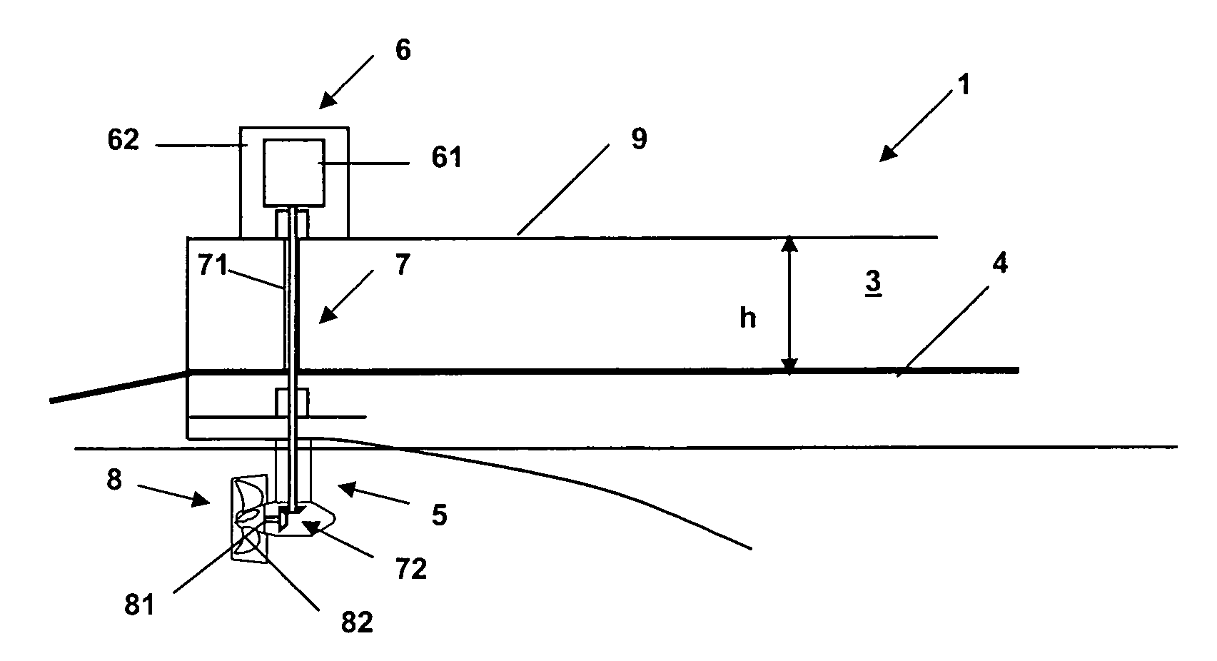
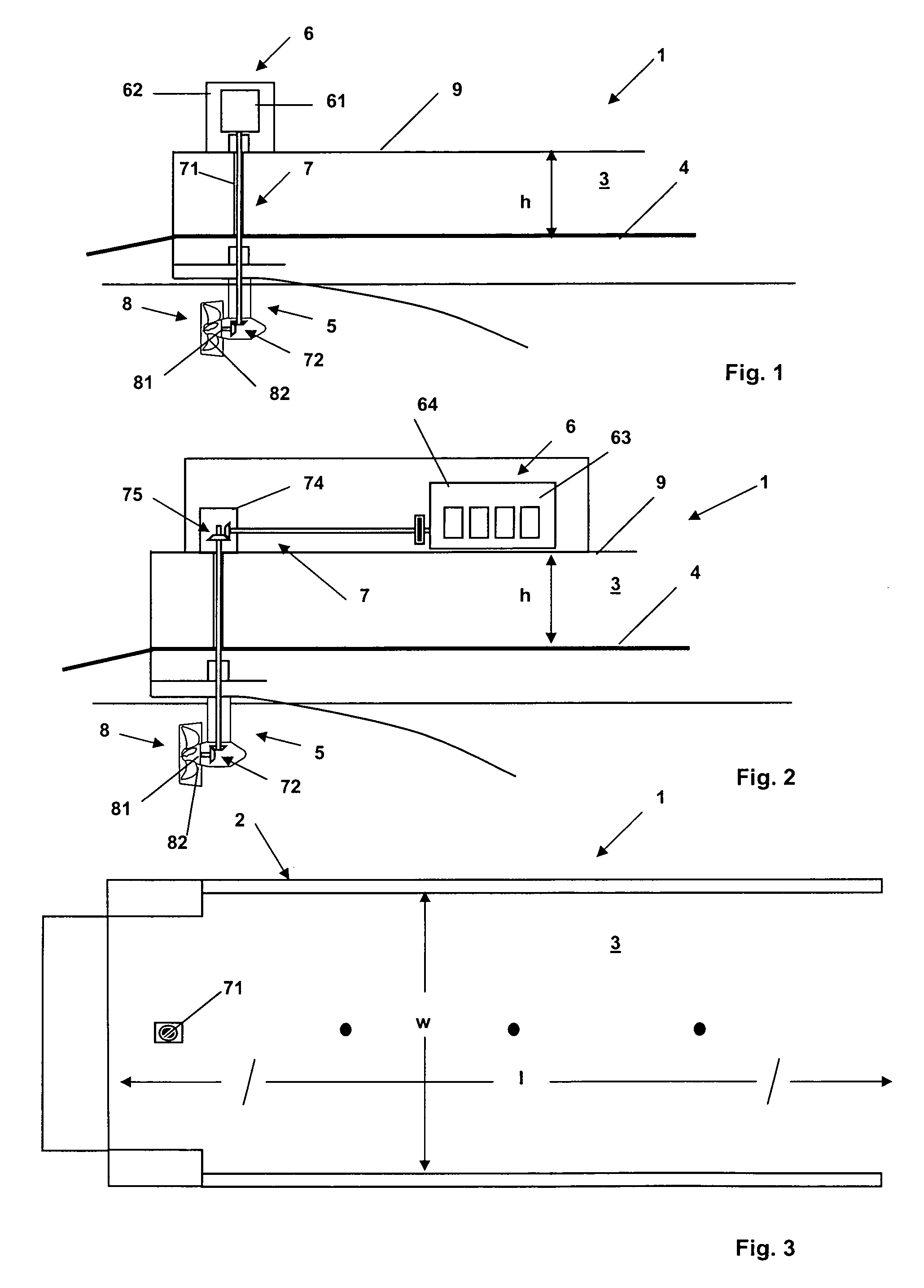
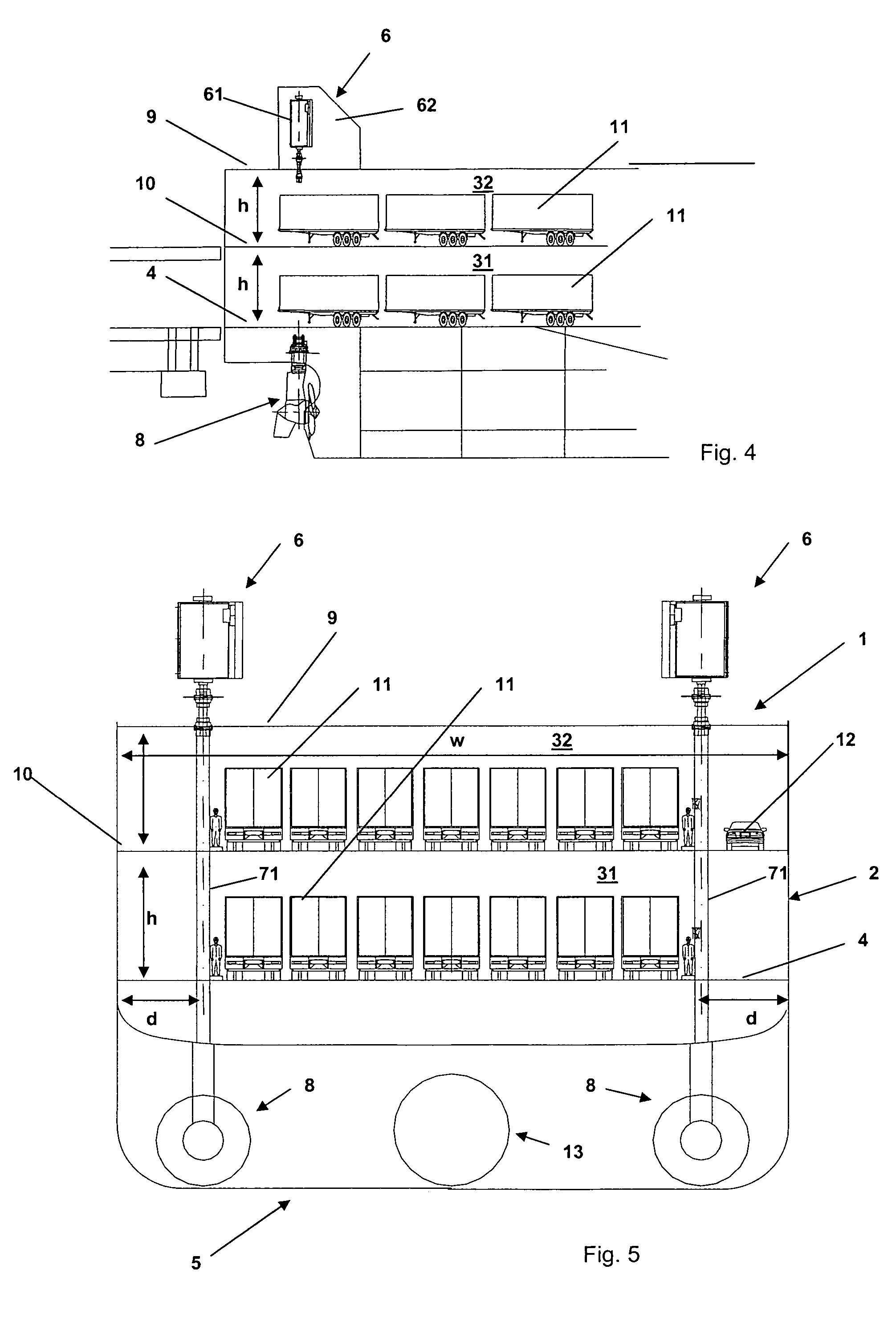
[0022]FIG. 1 shows the invention. In this embodiment the drive means 6 is an electrical motor 61, which is enclosed in a motor casing 62. The electrical motor is disposed above the loading space 3, on an upper deck 9. The steerable thruster unit 8 is below the bulkhead deck 4, i.e. below the loading space 3. The shaft arrangement 7 transferring power from the electrical motor 61 to the steerable thruster unit 8 comprises a vertical shaft section 71, which extends from the electrical motor 61 through the height h of the loading space 3 to a first angle gear 72 in the steerable thruster unit. The steerable thruster unit 8 is provided with a propeller 81 on a propeller shaft 82 connecting to the first angle gear 72. An arrangement like this is often called an L-drive.

[0023]As a consequence of the above arrangement, the only obstruction on the bulkhead deck 4 and in the loading space 3 due to the propulsion arrangement 5 is the narrow vertical shaft section 71 of the shaft arrangement 7...

second embodiment

[0024]FIG. 2 shows the present invention. In this embodiment the drive means comprises an internal combustion engine, e.g. a diesel engine, which is enclosed in an engine casing 64. The internal combustion engine 63 is disposed above the loading space 3 on an upper deck 9. The steerable thruster unit 8 is below the bulkhead deck 4, i.e. below the loading space 3. The shaft arrangement transferring power from the internal combustion engine 63 to the steerable thruster unit 8 comprises a substantially horizontally arranged or horizontally oriented shaft line 73 extending to a gear box 74 on the upper deck 9 above the loading space 3. The gear box 74 includes a second angle gear 75 for connecting the shaft line 73 to a vertical shaft section 71. The vertical shaft section 71 extends from the gear box 74 through the height h of the loading space 3 to a first angle gear 72 in the steerable thruster unit 8. The steerable thruster unit 8 is provided with a propeller 81 on a propeller shaft...


PUM


Abstract

A marine vessel includes a hull and has at least one load carrying facility defined by at least one loading space with a given height, a given width and a given length, whereby the loading space is provided on a bulkhead deck, and a propulsion arrangement, which includes at least one steerable thruster unit connected by a shaft arrangement to a drive means. In order to provide better access to the bulkhead deck for loading and unloading the marine vessel, the steerable thruster unit is arranged below the bulkhead deck and the drive means is arranged above the loading space. The shaft arrangement comprises a substantially vertical shaft section extending from the drive means above the loading space through the given height of the loading space and to the steerable thruster unit below the bulkhead deck.

Description

CROSS-REFERENCE TO RELATED APPLICATION[0001]This application claims priority under 35 USC 119 of Finnish Patent Application No. 20055068 filed Feb. 15, 2005.BACKGROUND OF THE INVENTION[0002]The present invention relates to a marine vessel comprising a hull, which includes at least one load carrying facility defined by at least one loading space with a given height, a given width and a given length, which loading space is provided on a bulkhead deck, and a propulsion arrangement, which includes at least one steerable thruster unit connected by a shaft arrangement to a drive means.[0003]In load carrying marine vessels, such as double end ferries, the propulsion arrangement may include one or more steerable thruster units for propelling and improving maneuverability of the vessel. Such thruster units are usually powered by electric motors or internal combustion engines, e.g. diesel engines. Freighters, container ships, RoRo and RoPax (RoRo passenger) are examples of other types of mari...

Claims


Application Information

Patent Timeline
Patent Type & Authority Patents(United States)
IPC IPC(8): B63H23/34B63BB63B25/00B63B35/54B63H5/08B63H5/125B63H21/14B63H21/17B63H23/04
CPCB63B25/008B63H23/04B63H5/125B63B35/54B63H5/08B63H2005/1256B63H21/14B63H21/17B63B25/04
Inventor LEVANDER, OSKAR
Owner WARTSILA FINLAND OY
Why Eureka
Try Eureka