
Method of making an article bearing a relief image using a removable film

a technology of relief image and removable film, which is applied in the direction of diffusion transfer process, photosensitive materials, instruments, etc., can solve the problems of difficult construction, long image creation time, and difficult image creation, so as to achieve less time, greater image sensitivity, and cost saving

Active Publication Date: 2007-10-09
KODAK POLYCHROME GRAPHICS +1
View PDF17 Cites 42 Cited by
  • Summary
  • Abstract
  • Description
  • Claims
  • Application Information

AI Technical Summary

Benefits of technology

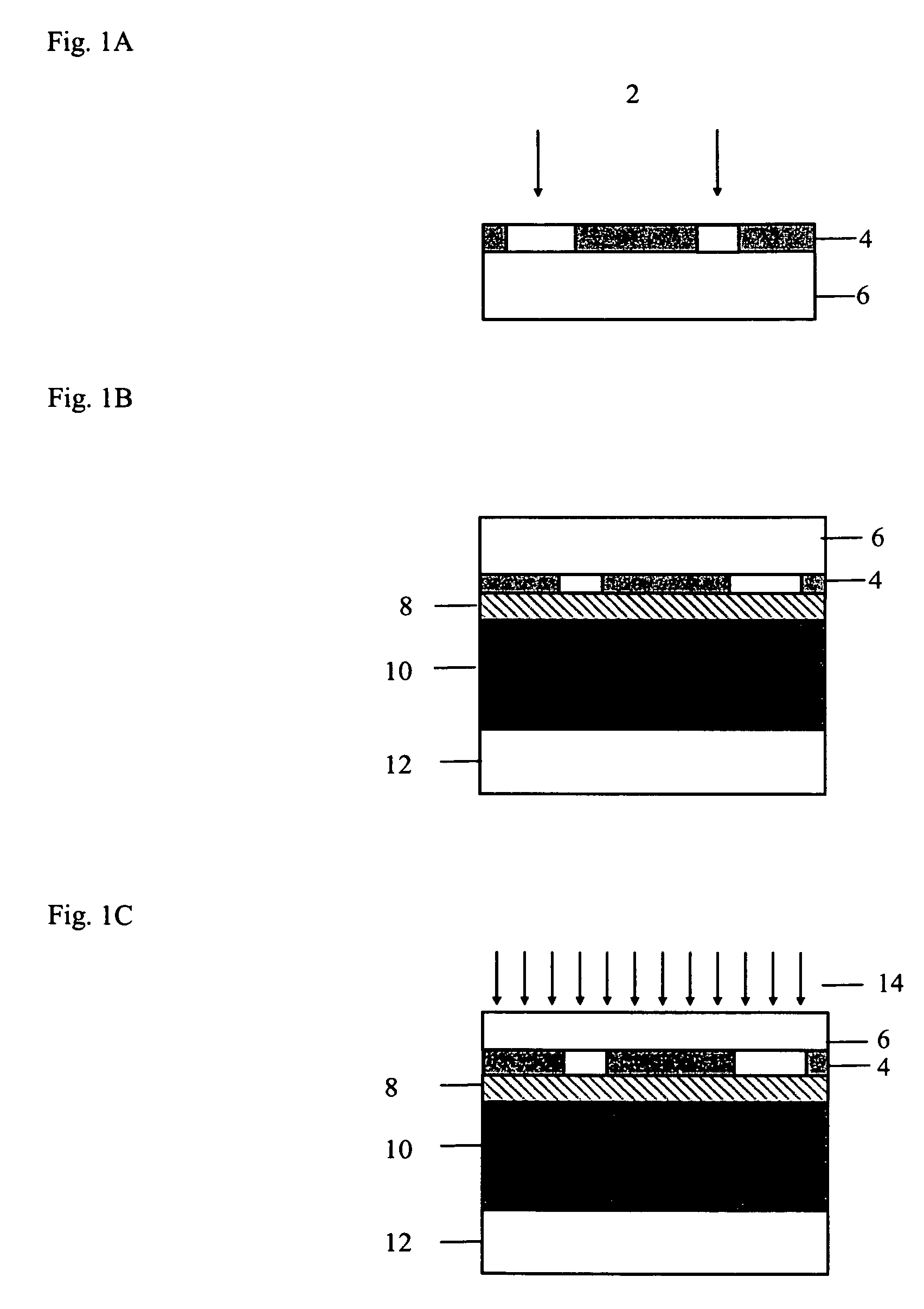
[0012]Yet another advantage of the invention is that the imaged film and mask image may be examined prior to transferring the imaged film to the imageable article. This permits the mask image to be “proofed” and corrected before a relief image is produced. Since the imageable article is typically much more expensive than the imageable film used for making the mask image, cost savings can be realized in the production of relief images. This is particularly the case when the imageable article is a flexographic precursor.
[0013]The methods provided by the present invention are advantageous as compared to the integral mask method of forming relief images. For example, the mask image may be made in significantly less time due to much greater imaging sensitivity than when an integral mask article is imaged. In some embodiments of the present invention, for example, only about 0.5 J / cm2 is required to form the mask image, as compared to 1.7-2.0 J / cm2 for integral masks; see U.S. Pat. No. 6,599,679 to Philipp, et al., Examples 1-3 reported at Table 2. Additionally, the mask image of the present invention may be reused whereas integral masks are developed with the uncured photosensitive material and are therefore not reusable.
[0014]The achievement of higher imaging sensitivity in making a mask image by the present invention allows the use of lower-cost imagers, at reasonable throughput, due to the fact that less powerful lasers are required than for previously known integral mask imaging systems. Since the imaging apparatus used in the practice of the invention are lower in cost and are more widely employed than the specialized flexographic imagers, the present invention permits the production of flexographic plates in more commercial settings. The use of commercially available computer-to-plate (“CTP”) devices for plates and proofing enables the use of the same imaging apparatus to make mask images (according to the present invention) for the production of flexographic plates, proofing films for lithographic printing plates, or CTP lithographic plates.
[0015]Since a transferable mask can be used in combination with a variety of photosensitive materials and applications, a transferable mask also provides flexibility in production. A transferable mask can also be used in combination with commercially available photosensitive materials on an as-needed basis.

Problems solved by technology

While elements having a laser ablatable mask layer allow direct imagewise exposure with a laser and do not require a separate masking device, the imaging time to create the mask is very long since the sensitivity to infrared radiation is low for the known integral mask systems.
Although higher sensitivity and, as such, shorter exposure time may be achieved, this construction suffers from undesirable adhesion of the ablatable mask layer to a coversheet that must be removed before exposure; see U.S. Pat. No. 6,599,679 to Philipp, et al. at C1 and C2, Table 2.
Higher sensitivity is difficult with the integral mask construction as the laser ablatable layer must satisfy a number of widely varying quality criteria; see U.S. Pat. No. 6,599,679, col.
Since these masks do not adhere to the photosensitive material, they tend to slip during the exposure step.
If optical contact is not achieved, the light in the exposure step may scatter when it reaches the pockets of air resulting in a relief image that is not an exact representation of the intended image on the mask.

Method used


Image

  • Method of making an article bearing a relief image using a removable film
  • Method of making an article bearing a relief image using a removable film
  • Method of making an article bearing a relief image using a removable film

Examples


example 1

[0186]A 7 mil thick polyester photosensitive substrate coated with a scratch resistant hardcoat, available from Courtaulds Performance Films (Martinsville, Va.), was coated with an ablatable layer solution containing the components listed in Table 1 as a 5% total solids solution in a 4.5:1 solvent mix of acetone and cyclohexanone using a #7 coating rod. The ablatable layer solution was dried for 5 minutes at 190° F. to form an ablatable layer having a coating weight of 50 mg / ft2 on the hardcoat.

[0187]

TABLE 1Components of the ablatable layer solution in Example 1ComponentPercent of total solidspolycyanoacrylate80.5%EPOLIGHT 117816.5%PC 3643.0%

[0188]An imageable material solution of the components listed in Table 2 was mixed as a 7.5% total solids solution in a 2:1 solvent mix of methyl isobutyl ketone and ethyl alcohol and applied to the ablatable layer using a #20 coating rod. The imageable material solution was heated in an 180° F. oven for 3 minutes to form a layer of imageable ma...

example 2

[0195]A sheet of Kodak Direct Image Thermal Recording Film 1401, available from Eastman Kodak (Rochester, N.Y.) was imaged with a halftone test pattern at 150 linescreen using round dots at 2400 dpi [above film was at 2540 dpi] using a DESERTCAT DC88 laser thermal imager, available from ECRM (Tewksbury, Mass.) emitting 830 nm radiation in the ablation mode at an energy level of 0.5 J / cm2 to form an imaged film.

[0196]A first FLEXCEL-SRH flexographic precursor (the “precursor”), available from Kodak Polychrome Graphics (Norwalk, Conn.), containing a photosensitive substrate, a photosensitive material, a releasing layer, and a cover sheet, was back-exposed with UV radiation through the photosensitive substrate on a KELLEIGH MODEL 310 PLATEMAKER available from the Kelleigh Corporation (Trenton, N.J.) for 31 seconds, and the cover sheet was peeled from the precursor. The imaged film was laminated to the precursor by placing the precursor in the entrance to an AGL hot roll laminator, avai...


PUM

PropertyMeasurementUnit
wavelengthaaaaaaaaaa
depthaaaaaaaaaa
thickaaaaaaaaaa

Abstract

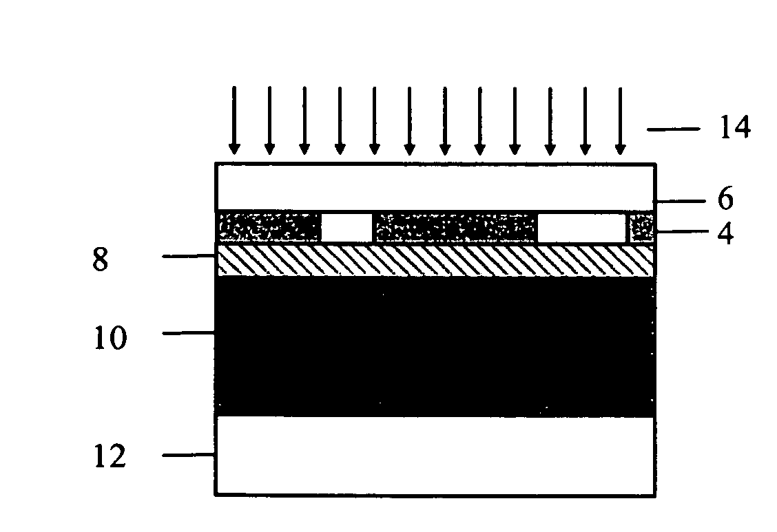
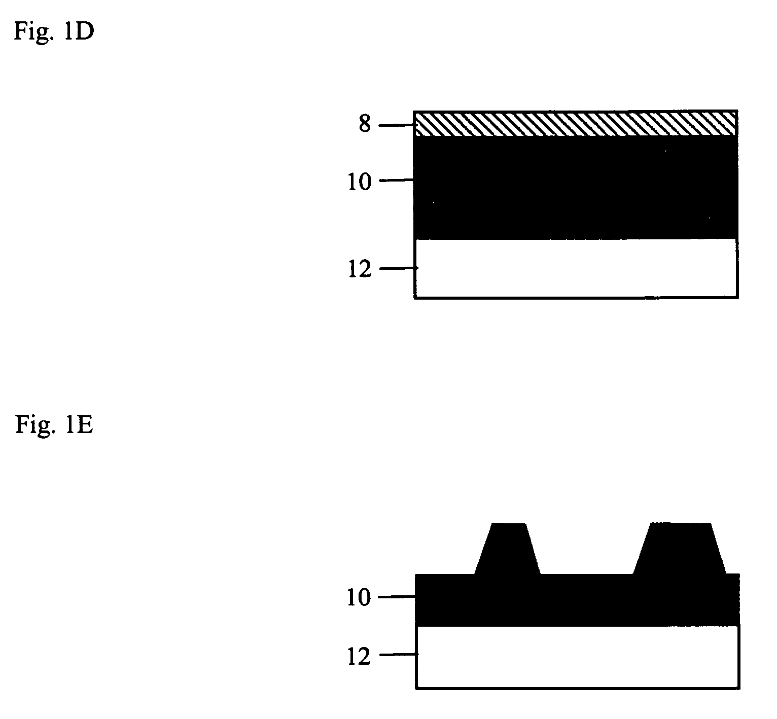
The invention is directed to methods of making an article bearing a relief image using a removable film. First, an imageable film that contains at least a mask substrate and an imageable material is imagewise exposed to imaging radiation to form an imaged film. The imaged film is then transferred to an imageable article, such as a flexographic printing plate precursor. The resulting assembly is exposed to curing radiation resulting in exposed and unexposed areas of photosensitive material on the imageable article. Following exposure to curing radiation, the imaged film is then removed from the imageable article. The imageable article is then developed with a suitable developer to form a relief image. The imaged film may then be reused to make additional articles bearing the relief image.

Description

BACKGROUND[0001]The present invention is directed to methods of making an article bearing a relief image using a removable film that may be reused to make additional articles bearing the relief image.[0002]Many methods of forming a relief image are known in the graphic arts. Photosensitive articles comprising an ablatable mask layer on the surface of a photosensitive polymer (or a so-called “integral mask”) may be made into articles bearing a relief image without the use of a photographic negative or other separate masking device. These photosensitive articles are formed into relief images by first imagewise exposing the photosensitive article with laser radiation (generally from an infrared laser under computer control) to selectively remove the mask layer in the exposed areas, and then overall exposing with an actinic radiation to cure the photosensitive layer in the unmasked areas. The remaining areas of the mask layer and the non-hardened portions of the photosensitive layer are...

Claims


Application Information

Patent Timeline
Patent Type & Authority Patents(United States)
IPC IPC(8): G03F7/20G03F1/00G03F1/02G03F7/30G03F7/36G03F1/88
CPCG03F1/56G03F7/2014G03F1/68
Inventor ZWADLO, GREGORY L.
Owner KODAK POLYCHROME GRAPHICS
Learn More