Toneable conduit and method of preparing same

a technology of toneable conduits and conduits, applied in the direction of pipes, pipe elements, pipe laying and repair, etc., can solve the problems of difficult to locate underground, difficult to couple this conduit with another conduit, and inability to always locate the conduit that is buried deep underground, so as to prevent moisture leakage, prevent damage to the cable within the conduit, and detect the effect of moistur

Inactive Publication Date: 2007-10-09
DURA LINE CORP A CORP OF KY
View PDF38 Cites 24 Cited by
  • Summary
  • Abstract
  • Description
  • Claims
  • Application Information

AI Technical Summary

Benefits of technology

[0009]The present invention provides a conduit that can transmit a signal over great distances and that can therefore be readily detected by toning equipment. In addition, the conduit of the invention can be readily coupled to provide extended lengths of conduit. In particular, the present invention uses a continuous wire to provide the toning signal that is capable of being torn out through the conduit to allow the conduit to be coupled over extended lengths by forming an electrical connection between the wire of adjacent segments of conduit. In addition, the connectors used for the conduit can be connected flush against the exterior surface of the conduit to prevent the leakage of moisture into the conduit and thus prevent damage to the cable within the conduit. The conduit of the invention also has excellent crush strength as is desired in the art. The conductive wire also includes a coating that allows the conductive wire to be protected in the underground environment and that facilitates the continuous production of the conduit of the invention.
[0010]The above advantages are achieved through the use of a toneable conduit that includes an elongate polymeric tube having a wall with an interior surface, an exterior surface, and a predetermined wall thickness. A channel extends longitudinally within the wall of the elongate polymeric tube and a stabilizing rib preferably extends longitudinally along the interior surface of the wall of the elongate polymeric tube and is located radially inward from the channel. A continuous wire is coincident with the channel in the elongate polymeric tube and is preferably coated with a coating composition that prevents the wire from adhering to the polymer melt used to form the elongate polymeric tube. Preferably, the wire has a tensile strength of at least about 150 lbs. and is preferably a copper-clad steel wire, copper-clad aluminum wire, copper wire or tin copper wire. More preferably, the wire is copper-clad steel wire. The wire also preferably has a diameter from about 0.32 mm to about 2.59 mm. More preferably, the wire has a diameter of 1.02 mm. In accordance with the invention, the wire is capable of transmitting a toning signal to allow the conduit to be detected by toning equipment and is capable of being torn out of the polymeric tube to allow the conduit to be coupled. The wire is preferably coated with a coating composition that is formed of a high melting temperature polymeric material, preferably having a melting temperature of at least about 500° F. Preferably, the high melting temperature polymeric material is selected from the group consisting of fluoropolymers, polyamides, polyesters, polycarbonates, polypropylene, polyurethanes, polyacetals, polyacrylics, epoxies and silicone polymers and is more preferably polytetrafluoroethylene. Preferably, the conduit is formed of polyethylene or polyvinyl chloride and more preferably high-density polyethylene (HDPE). The conduit also preferably has a smooth exterior surface and can further include at least one additional rib (in addition to the stabilizing rib) extending longitudinally along the interior surface of the elongate polymeric tube to facilitate the installation of cable within the conduit.

Problems solved by technology

One issue with conduit is that it can be difficult to locate underground when it is either empty or it contains a non-metallic cable, such as a fiber optic cable.
Although these types of detection devices are useful, they cannot always locate conduit that is buried deep underground (e.g. greater than 5 feet).
Although these types of constructions have found use, it is difficult to couple this conduit with another conduit because the exterior rib prevents the connector from fitting flush onto the conduit.
As a result, moisture can enter the conduit at the connection and can cause damage to the cable installed therein.
In addition, the exterior rib can cause problems during installation in that the exterior rib and associated wire can be ripped off of the conduit if the conduit is being installed by directional boring or plowing methods.
Although this type of conduit can be detected by the metal detection devices discussed above, it cannot be detected by conventional toning equipment because a signal cannot be transmitted along the conduit.
Although the strip or ribbon in these constructions can be detected by conventional metal detecting equipment, it does not have a suitable construction for transmitting a toning signal for extended distances and at the depths desired in the art.

Method used


Image

  • Toneable conduit and method of preparing same
  • Toneable conduit and method of preparing same
  • Toneable conduit and method of preparing same

Examples


Embodiment Construction

[0023]In the drawings and the following detailed description, preferred embodiments are described in detail to enable practice of the invention. Although the invention is described with reference to these specific preferred embodiments, it will be understood that the invention is not limited to these preferred embodiments. But to the contrary, the invention includes numerous alternatives, modifications and equivalents as will become apparent from consideration of the following detailed description and accompanying drawings. In the drawings, like numbers refer to like elements throughout.

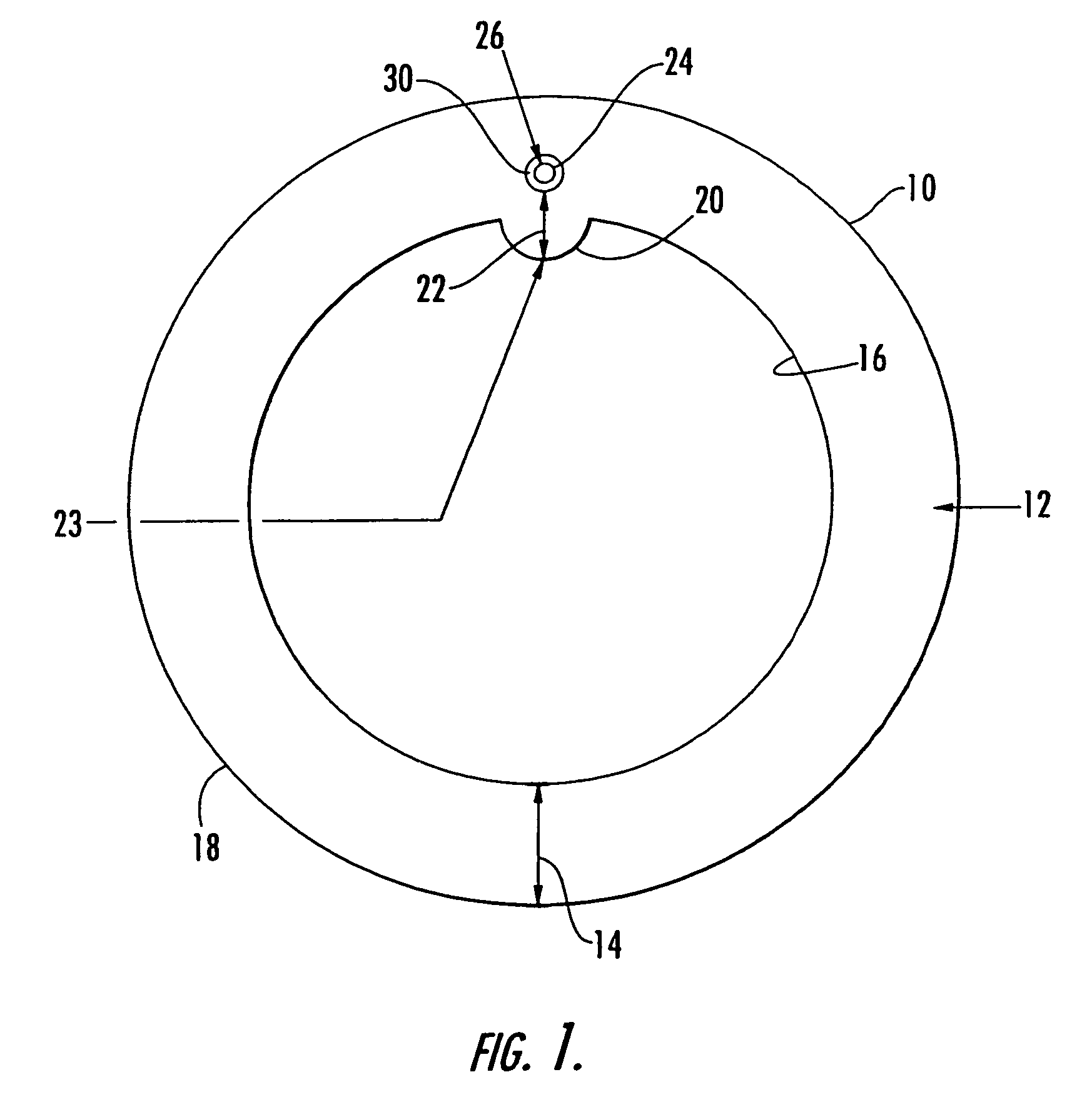
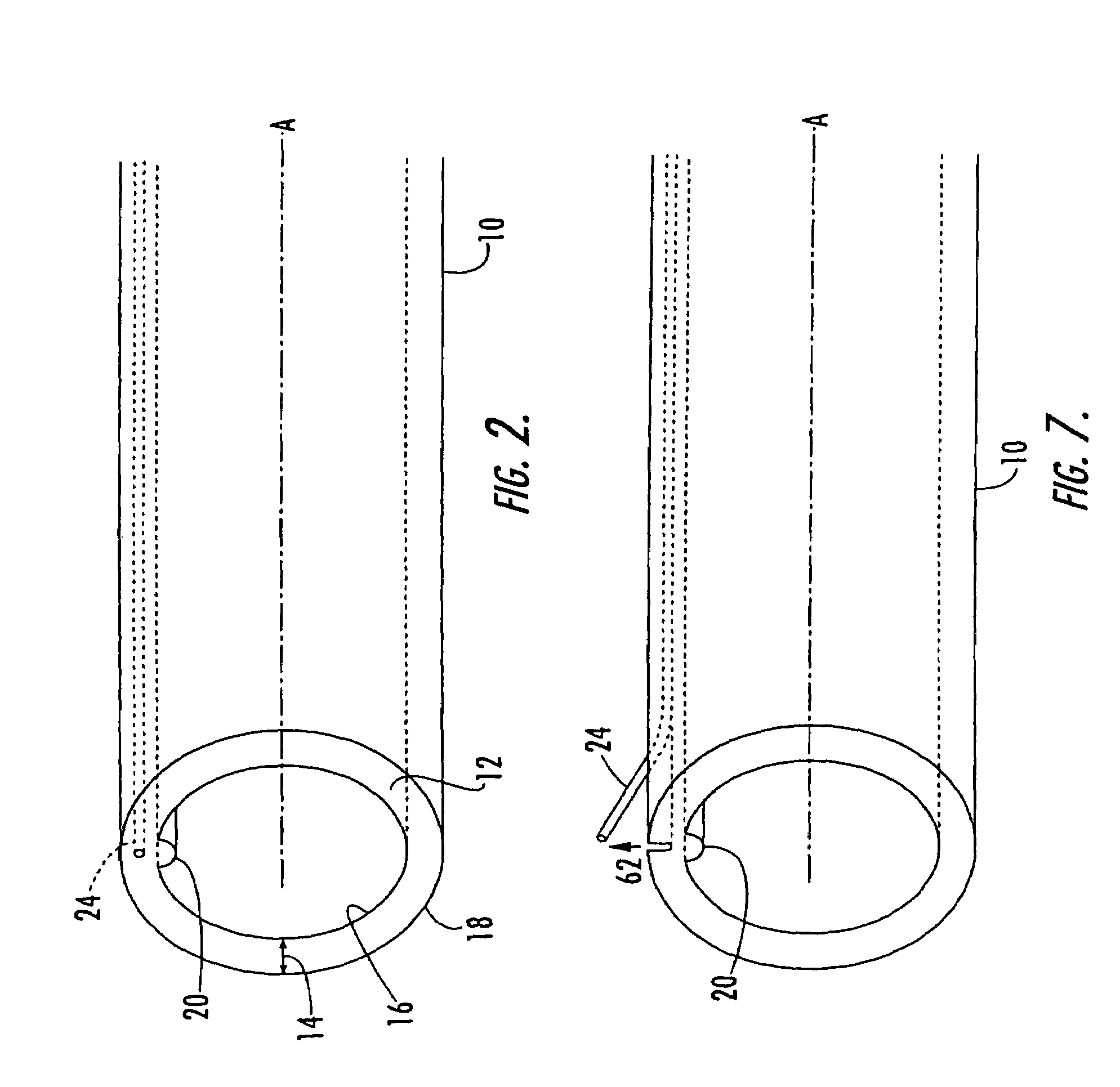
[0024]FIGS. 1 and 2 illustrate a toneable conduit according to the present invention. As shown in these figures, the conduit is formed of an elongate polymeric tube 10 that includes a wall 12 having a predetermined thickness 14 and further includes an interior surface 16 and an exterior surface 18. The exterior surface 18 is preferably smooth so that the conduit can be effectively coupled as discusse...


PUM

PropertyMeasurementUnit
melting temperatureaaaaaaaaaa
diameteraaaaaaaaaa
diameteraaaaaaaaaa

Abstract

The invention is a toneable conduit that can transmit a signal and be readily detected by toning equipment. The conduit can be coupled with other conduit to provide extended lengths of conduit. The toneable conduit includes an elongate polymeric tube having a wall with an interior surface, an exterior surface, and a predetermined wall thickness. A channel preferably extends longitudinally within the wall of the elongate polymeric tube; a stabilizing rib extends longitudinally along the interior surface of the wall of the elongate polymeric tube and is located radially inward from the channel. A continuous wire is coincident with the channel in the elongate polymeric tube and preferably coated with a composition that prevents it from adhering to the polymer melt that forms the elongate polymeric tube. The present invention includes methods of making the toneable conduit and methods of coupling a first toneable conduit with a second toneable conduit.

Description

CROSS REFERENCE TO RELATED APPLICATIONS[0001]This application is a continuation of copending U.S. patent application Ser. No. 10 / 830,754, filed Apr. 23, 2004, which is a divisional of U.S. patent application Ser. No. 10 / 158,810, filed May 30, 2002 now abandoned, which is a continuation-in-part of copending U.S. patent application Ser. No. 09 / 989,289, filed Nov. 20, 2001.FIELD OF THE INVENTION[0002]The present invention relates to toneable conduit and more particularly to toneable conduit that can be detected by conventional toning equipment and that includes a wire that is capable of being torn out of the conduit to allow the conduit and wire to be coupled.BACKGROUND OF THE INVENTION[0003]Conduit is often buried to provide an underground path for cables such as coaxial cables and fiber optic cables. In particular, conduit is typically formed of a plastic material that protects the coaxial cables and fiber optic cables from the moisture and other hazards of the underground environmen...

Claims


Application Information

Patent Timeline
Patent Type & Authority Patents(United States)
IPC IPC(8): H02G3/08B29C48/06B29C48/09B29C48/32F16L1/11F16L9/12G02B6/44H02G3/04H02G3/06H02G9/06
CPCB29C47/02B29C47/025B29C47/28F16L1/11F16L9/125F16L11/127F16L25/01G02B6/4459G02B6/447H02G3/0481H02G3/06H02G9/06B29C47/0023B29C47/0004Y10T428/139B29K2023/06B29K2023/065B29K2023/12B29K2027/06B29K2027/18B29K2067/00B29K2069/00B29K2075/00B29K2077/00B29K2705/00B29K2995/0005G02B6/4495H02G2200/20H02G1/08H02G9/065B29C48/15B29C48/022B29C48/09B29C48/154B29C48/34B29C48/06G02B6/562G02B6/4431
Inventor MORROW, JASON NORMANWARD, JR., ROBERT MILLERKALE, ZEB LEONARDBAILEY, MICHAEL RAYGEMME, CHRISTOPHERBOLLINGER, GEORGELUMLEY, SCOTT
Owner DURA LINE CORP A CORP OF KY
Why Eureka
Try Eureka