Lens meter

a technology of lens meter and meter body, which is applied in the direction of material analysis, phase-affecting property measurement, instruments, etc., can solve the problems of increasing production cost, taking a lot of trouble in measuring progressive power lenses, and a large amount of time to obtain the refractive power distribution of progressive power lenses. , to achieve the effect of low cost structur

Active Publication Date: 2007-10-09
NIDEK CO LTD
View PDF19 Cites 12 Cited by
  • Summary
  • Abstract
  • Description
  • Claims
  • Application Information

AI Technical Summary

Benefits of technology

[0007]An object of the invention is to overcome the problems described above and to provide a lens meter which makes it possible to measure refractive power distribution of a progressive power lens and display a map of the refractive power distribution with a low-cost structure.

Problems solved by technology

Though the lens meter which measures the optical characteristics in one measurement position is enough for measurement of a single vision lens, it takes a lot of trouble in measurement of a progressive power lens before finding the distance portion and the near portion.
Further, it takes much time to obtain refractive power distribution of the progressive power lens.
On the other hand, the lens meter which measures the optical characteristics in the plurality of measurement positions can easily obtain the refractive power distribution of the progressive power lens; however, requirements are extensively increased in order to meet necessity and size of optical members such as a screen and an image forming lens, size of a photo-receiving surface of the photo-sensor, performance of a calculation part, and the like for obtaining refractive powers in the respective measurement positions within the measurement region covering the wide range extending over the distance portion, the progressive portion and the near portion, and thereby the cost of production is raised.
Further, since the measurement cannot be performed while bringing heights to a rear surface of the lens within the measurement region to be almost constant, measurement results on the distance portion and the near portion positioned in a peripheral part within the measurement region possesses low reliability.

Method used


Image

  • Lens meter
  • Lens meter
  • Lens meter

Examples


Embodiment Construction

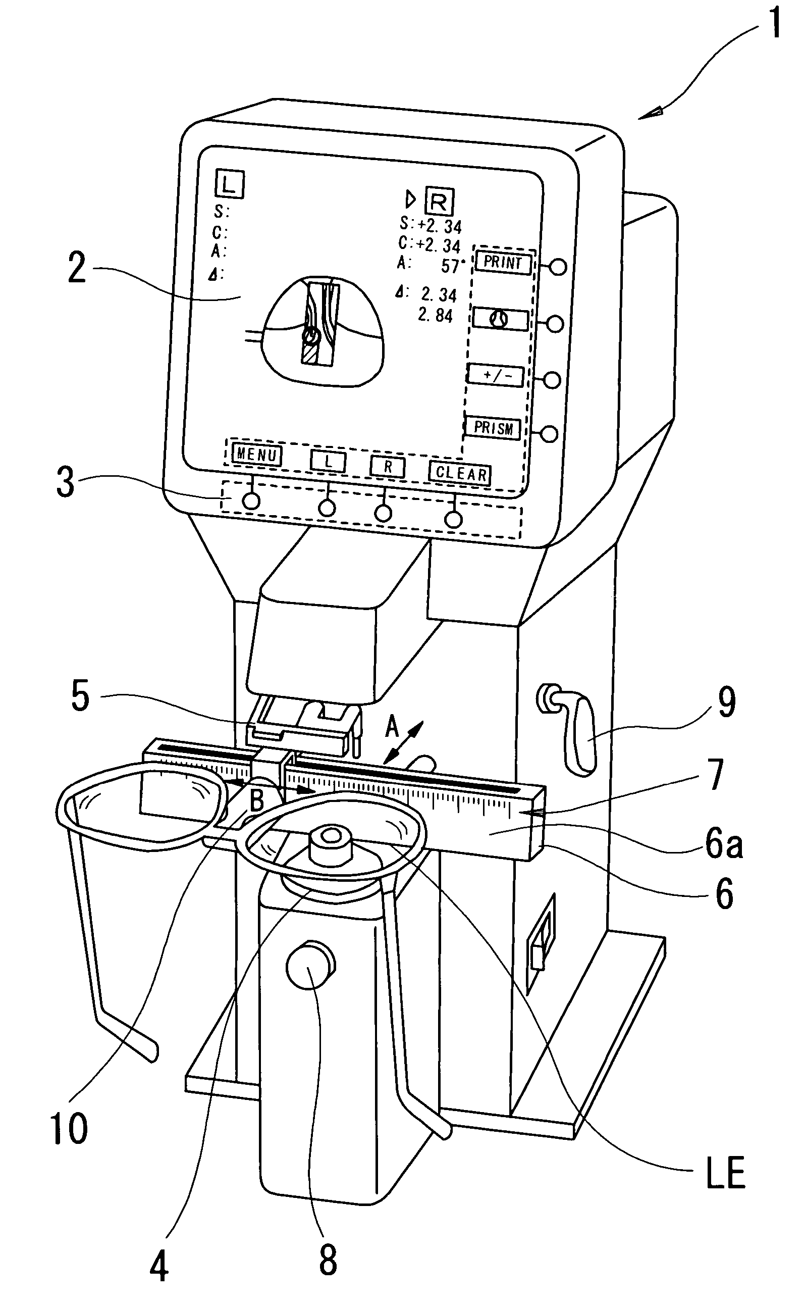
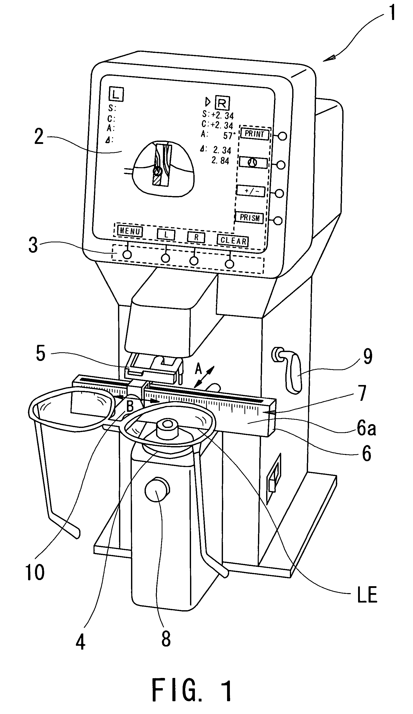
[0020]A detailed description of one preferred embodiment of a lens meter embodied by the present invention is provided below with reference to the accompanying drawings. FIG. 1 is a schematic external view of the lens meter consistent with the preferred embodiment of the present invention.

[0021]On a display 2 such as a liquid crystal display arranged at the top of a body 1 of the lens meter, information necessary for measurement, measurement results, and the like are displayed. At the press of one of switches 3 corresponding to switch displays on the display 2, necessary instructions such as measurement mode switching are inputted.

[0022]A subject lens LE to be measured is mounted on a nosepiece (lens rest) 4, and a lens holder 5 is moved downward (to a nosepiece 4 side) to stably hold the lens LE mounted on the nosepiece 4.

[0023]When measuring the lens LE in frames, a frame table (lens table) 6 movable in a back / forth direction (the arrow A direction in FIG. 1) is brought into conta...


PUM


Abstract

A lens meter for measuring refractive power distribution of a progressive power lens and displaying its distribution map, has a lens rest having an aperture, an optical system including an axis, a source projecting a light bundle along the axis, a plate having targets and a two-dimensional image sensor detecting images by the bundle passing through the lens, aperture and plate, a part calculating the distribution within a measurement region from detection results, a part detecting a lens-position in a two-dimensional direction orthogonal to the axis, a device guiding movement on the rest to shift the measurement region and obtaining the distribution within an analysis region including distance, progressive and near portions, a part storing the distribution in the measurement region in association with the detected position, a display part, and a part controlling to display the distribution map within the analysis region based on the stored distribution and position.

Description

BACKGROUND OF THE INVENTION[0001]1. Field of the Invention[0002]The present invention relates to a lens meter for measuring optical characteristics of a lens.[0003]2. Description of Related Art[0004]Conventionally, there is known a lens meter which projects a measurement light bundle onto a subject lens to be measured which is placed on a measurement optical axis, and photo-receives the measurement light bundle having passed through the subject lens by the use of a photo-sensor, and then obtains optical characteristics such as refractive power of the subject lens based on the photo-receiving results. For this kind of lens meter, proposed initially was one which measures optical characteristics in one measurement position (measurement point) of the subject lens, and after that, proposed recently has been one which measures optical characteristics in a plurality of measurement positions (measurement points) at a time within a measurement region covering a wide range extending over a d...

Claims


Application Information

Patent Timeline
Patent Type & Authority Patents(United States)
IPC IPC(8): G01B9/00G01M11/02
CPCG01M11/0228
Inventor HAYASHI, AKIHIROKAJINO, TADASHIOHTSUKI, KAN
Owner NIDEK CO LTD
Why Eureka
Try Eureka