Rotation angle detection apparatus and rotary disk for same

a detection apparatus and rotary disk technology, applied in the direction of mechanical measuring arrangements, instruments, using mechanical means, etc., can solve the problems of deteriorating detection accuracy of the sensor head, difficult to reduce manufacturing costs, and inability to achieve a high degree of coaxiality or fitness. , to achieve the effect of low cost structure and high accuracy

Inactive Publication Date: 2006-03-28
CANON KK
View PDF10 Cites 7 Cited by
  • Summary
  • Abstract
  • Description
  • Claims
  • Application Information

AI Technical Summary

Benefits of technology

[0019]An object of the present invention is to solve the above-described problem to provide a rotation angle detection apparatus that can detect the rotation angle with high accuracy while coping with a change in the ambient temperature with a low cost structure. It is also an object of the present invention to provide a rotary disk of that apparatus.

Problems solved by technology

Thus, manufacturing of a conventional rotary encoder involves many processes and it is difficult to reduce the manufacturing cost.
In addition, since the rotary scale 7 is formed on a thin glass plate or a thin metal plate by etching or as a photoengraving PET film attached thereto, it is impossible to attain a high degree of precision in coaxiality or in fitness.
Thus, the detection accuracy of the sensor head would be deteriorated.
In order to solve the above-described problem, it is necessary to reduce the mounting tolerance of the rotary disk 18 to the sensor head 11 with respect to the thrust direction as small as possible, which involves an increase in the manufacturing cost.

Method used


Image

  • Rotation angle detection apparatus and rotary disk for same
  • Rotation angle detection apparatus and rotary disk for same
  • Rotation angle detection apparatus and rotary disk for same

Examples


first embodiment

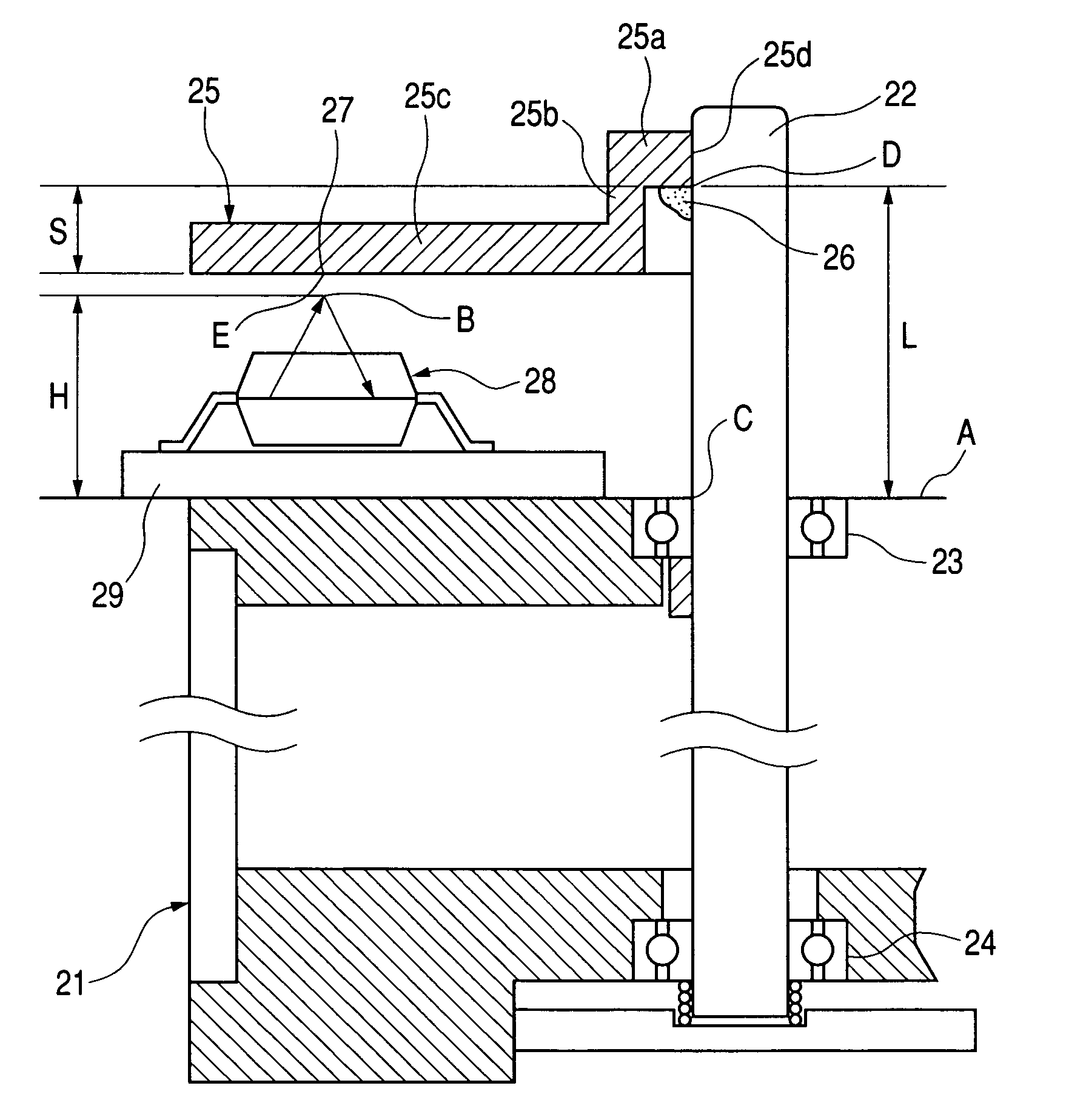
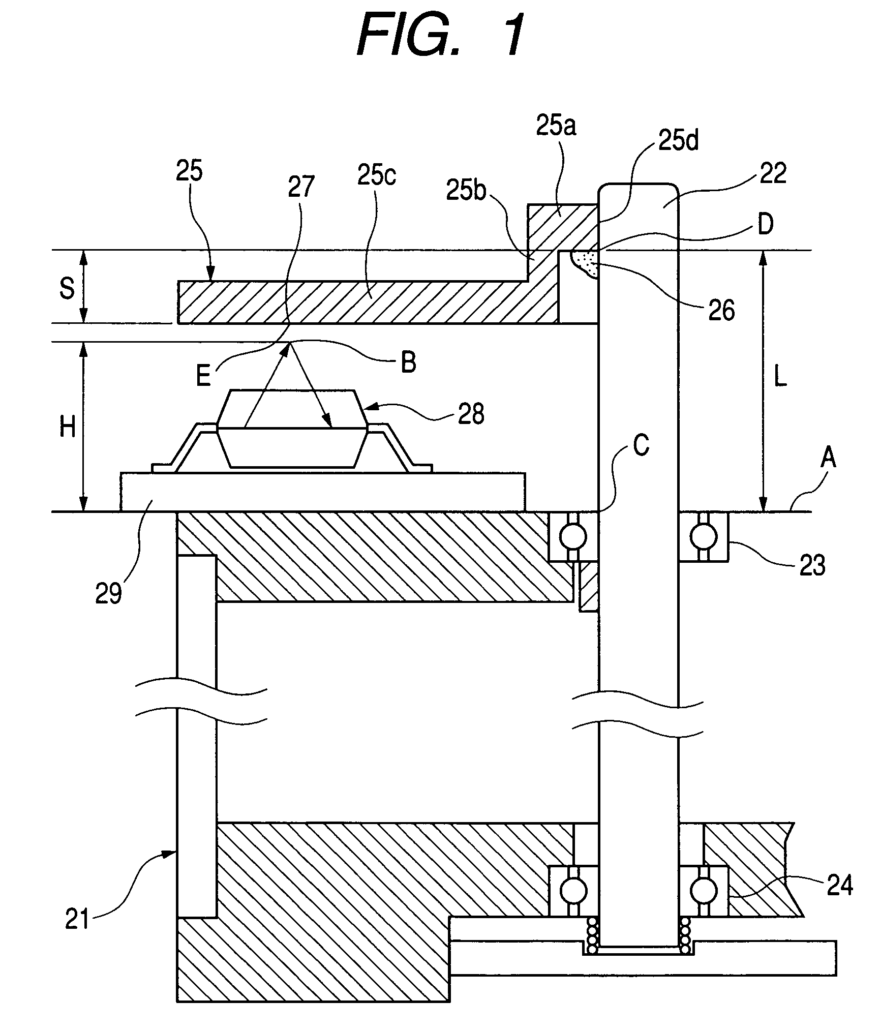
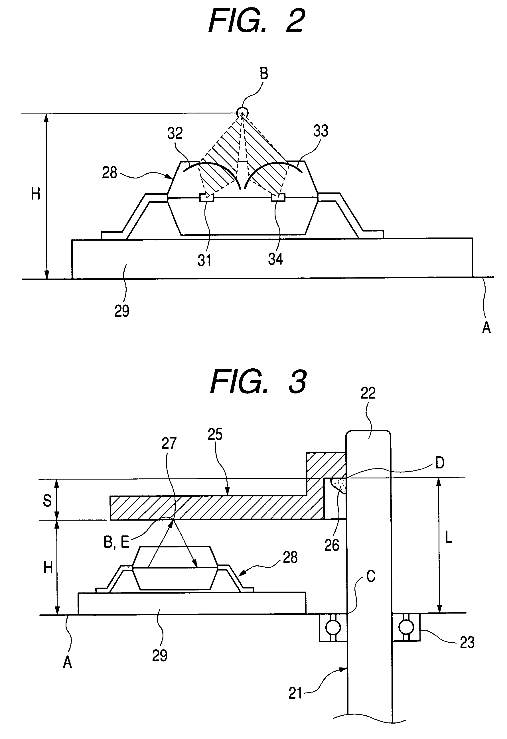
[0038]FIG. 1 is a cross sectional view showing the principal part of the present invention as a rotation angle detection apparatus in the form of a reflective rotary encoder. A rotary shaft 22 of a motor 21 is rotatably supported by an upper bearing 23 and a lower bearing 24. A rotary disk 25 is fitted to the upper portion of the rotary shaft 22. The rotary disk 25 is bonded to the rotary shaft 22 by adhesive 26. On the lower surface of the rotary disk 25, there is provided a rotation angle information record part 27, which includes one or more reflecting elements arranged regularly in the circumferential direction. The motor 21 has a reference mount surface A on which a reflection type sensor head 28 is attached with an electric circuit board 29 between.

[0039]The rotary disk 25 is made by integral molding using a light transmissive synthetic resin material. The rotary disk 25 is provided with a fixing portion 25a having a disk shape to be fixed to the rotary shaft 22, a cylindrical...

fifth embodiment

[0055]FIG. 9 is a cross sectional view showing the principal portion of the apparatus according to the present invention. In this apparatus, a rotary disk 53 is attached to the top surface of a rotary shaft 52 of a motor 51 by adhesive 54. On the top surface of the rotary shaft 52, there is provided a groove 52a in which the adhesive 54 is applied.

[0056]The rotary disk 53 is provided with a fixing portion 53a to be placed on the top surface of the rotary shaft 52, a cylindrical portion 53b extending downwardly from the outer periphery of the fixing portion 53a and a disk body portion 53c extending horizontally and outwardly from the lower portion of the cylindrical portion 53b. The interior of the cylindrical portion 53b is formed as a fitting hole 53d into which the rotary shaft 52 is fitted in such a way that a small clearance would remain between the outer circumferential surface of the rotary shaft 52 and the inner circumferential surface of the fitting hole 53d. A rotation angl...

sixth embodiment

[0057]FIG. 10 is a cross sectional view showing the principal portion of an apparatus according to the present invention. In this apparatus, a rotary disk 63 is attached to the top surface of a rotary shaft 62 of a motor 61 by a washer 64 and a set screw 65. On the top surface of the rotary shaft 62, there is formed a screw hole 62a into which the set screw 65 is to be threaded.

[0058]The rotary disk 63 is provided with a disk-like fixing portion 63a to be fixed to the top surface of the rotary shaft 62, a cylindrical portion 63b extending downwardly from the outer periphery of the fixing portion 63a and a disk body portion 63c extending horizontally and outwardly from the lower portion of the cylindrical portion 63b. The interior of the cylindrical portion 63b is formed as a fitting hole 63d into which the rotary shaft 62 is fitted in such a way that a small clearance would remain between the outer circumferential surface of the rotary shaft 62 and the inner circumferential surface ...


PUM


Abstract

A rotation information record surface of a rotary disk is disposed at an intermediate position between a fixing point of the rotary disk and a rotary shaft and a fixing position of a detection head, so that a stable gap can be obtained with a variation due to thermal expansion being reduced. In order to attain this, the fitting portion of the rotary disk is shaped to have a first fitting portion and a second fitting portion. The first fitting portion is provided for attaining satisfactory coaxiality, and the second fitting portion is adapted to form a clearance into which bonding means such as an adhesive is to be infused. With the above structure, an optimum detection position (i.e. an optimum gap position) would not be varied by a change in the ambient temperature.

Description

BACKGROUND OF THE INVENTION[0001]1. Field of the Invention[0002]The present invention relates to a rotation angle detection apparatus and particularly relates to an apparatus, such as a resin rotary encoder, provided with a rotary disk. The invention also relates to a rotary disk used in such an apparatus.[0003]2. Related Background Art[0004]Many of the conventional rotary encoders are optical rotary encoders that detect rotation angle information optically or magnetic rotary encoders that detect rotation angle information magnetically. The optical rotary encoder is either a transmissive rotary encoder in which a light flux is adapted to be transmitted by a rotation angle information record part or a reflective rotary encoder in which a light flux is adapted to be reflected by a rotation angle information record part.[0005]FIG. 11 shows, by way of example, a conventional transmissive rotary encoder. In this rotary encoder, a motor 1 supports a rotary shaft 2 by bearings 3 and 4. An ...

Claims


Application Information

Patent Timeline
Patent Type & Authority Patents(United States)
IPC IPC(8): G01D5/34G01D5/245G01D5/347
CPCG01D5/34738
Inventor IGAKI, MASAHIKOATSUTA, AKIO
Owner CANON KK
Why Eureka
Try Eureka