Low total excursion dispersion maps

a technology of dispersion map and total excursion, applied in the field of optical communication system, can solve the problems of degrading optical pulses, increasing transmission errors, and maps that do not completely correct for pulse degradation caused by nonlinear optical effects, and achieve the effect of reducing pulse degradation

Inactive Publication Date: 2007-10-09
LUCENT TECH INC
View PDF11 Cites 19 Cited by
  • Summary
  • Abstract
  • Description
  • Claims
  • Application Information

AI Technical Summary

Benefits of technology

[0014]The various embodiments relate to long-haul all-optical transmission systems and processes that produce low total excursion. These maps reduce pulse degradation from nonlinear optical effects when transmission is performed in the pseudo-linear transm

Problems solved by technology

Both effects degrade optical pulses in ways that increase transmission errors.
While full-span compensation maps do compensate very well for the pulse degradation caused by chromatic dispersion, these maps do not completely correct for the pulse degradation caused by nonlinear optical effects.

Method used


Image

  • Low total excursion dispersion maps
  • Low total excursion dispersion maps
  • Low total excursion dispersion maps

Examples


Embodiment Construction

[0041]Herein, a long haul, all-optical communication path includes a series of transmission spans whose combined length is more than about 1,000 kilometers. In such a path, the series of transmission spans may be 2,000 kilometers long or longer.

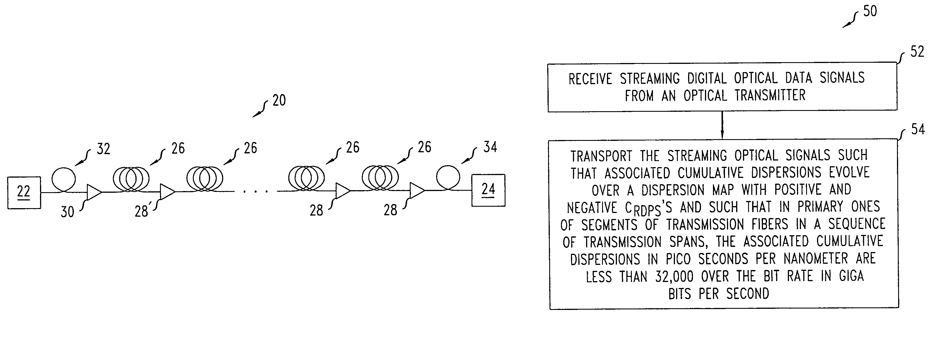
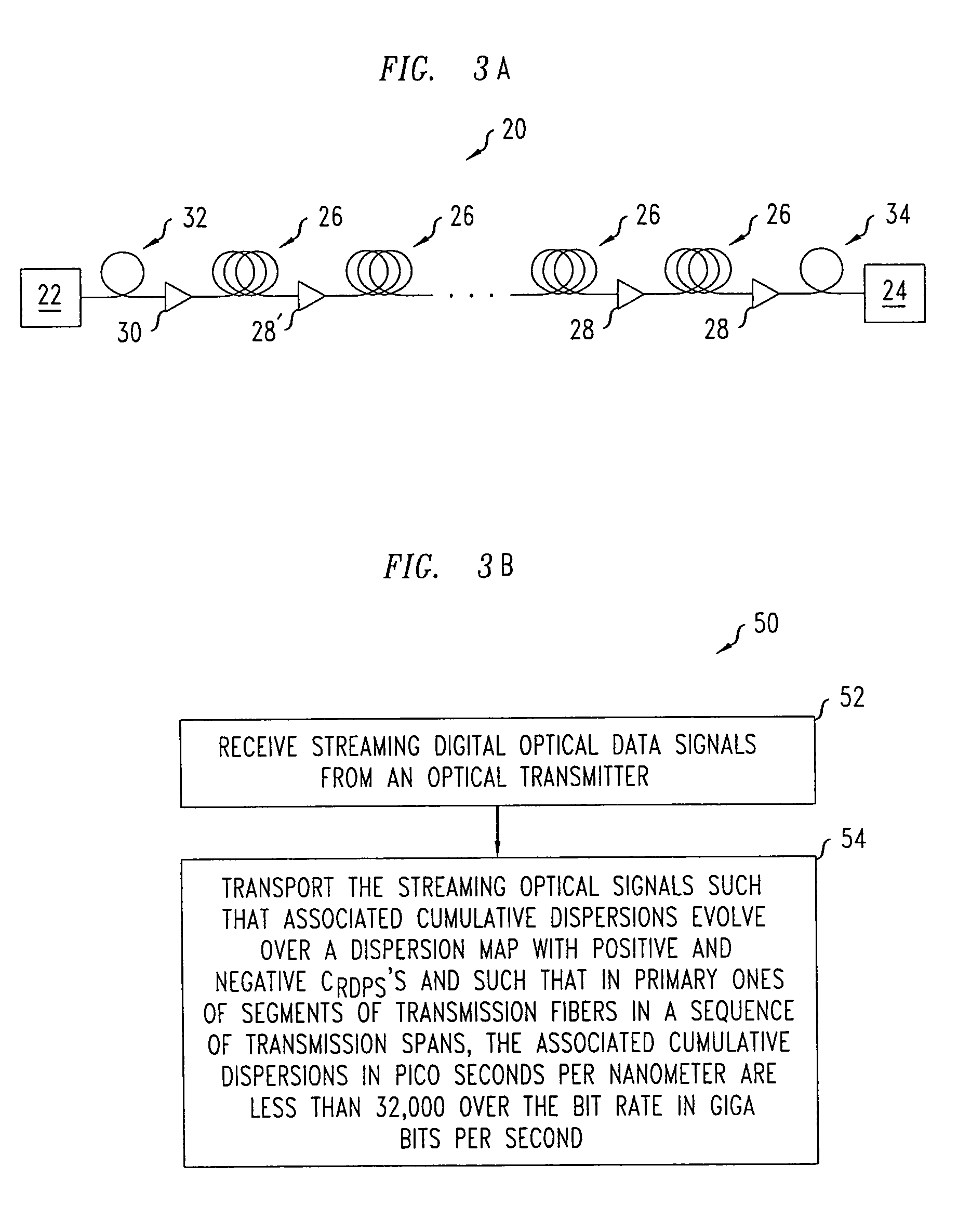
[0042]FIG. 3A shows a long haul, all-optical, communication path 20 that connects an optical transmitter 22, which encodes digital data into a stream of digital optical data signals, to an optical receiver 24, which extracts digital data from such streams of digital optical data signals. The stream of digital data may encode the data as a stream of optical pulses or as a stream of phase modulations on an optical carrier and may encode the data in an optical return-to-zero (RZ) format or an optical non-return-to-zero (NRZ) format. The optical communication path 20 includes the optical transmission spans 26 and in-line optical amplifiers 28, which are disposed between adjacent pairs of the optical transmission spans 26. Each optical transmissio...


PUM


Abstract

A process optically transports digital data over an all-optical long-haul communication path. The process includes transporting digital optical data signals at a selected bit rate and a selected wavelength over a sequence of transmission spans. The sequence includes 70 percent or more of the spans of the long-haul all-optical communication path. Each span of the sequence has a primary local maximum optical power point for the wavelength on a transmission fiber and nearest to an input of the span. The transporting causes a cumulative dispersion of each signal to evolve such that residual dispersions per span are positive over some of the spans and are negative over other of the spans. At the primary local maximum power points, magnitudes of cumulative dispersions of the signals in pico seconds per nanometer remain at less than 32,000 times the inverse of the bit rate in giga bits per second.

Description

[0001]This is a continuation-in-part application of application Ser. No. 10 / 442,287, filed May 20, 2003.BACKGROUND[0002]1. Field of the Invention[0003]The invention relates to optical communication systems and processes.[0004]2. Discussion of the Related Art[0005]In optical communications systems, transmission optical fibers cause chromatic dispersion and nonlinear optical effects. Both effects degrade optical pulses in ways that increase transmission errors. To reduce the pulse degradation caused by chromatic dispersion, optical communication systems typically incorporate dispersion compensation devices, e.g., dispersion compensating fibers (DCFs), dispersion compensating interferometers, or dispersion compensating grating systems, to compensate for chromatic dispersion. To reduce the pulse degradation caused by nonlinear optical effects, long-haul optical communication systems typically manage dispersion through special processes and special dispersion maps.[0006]The special proce...

Claims


Application Information

Patent Timeline
IPC IPC(8): H04B10/00H04B10/02H04B10/18H04B10/2581
CPCH04B10/25253
Inventor CHOWDHURY, AREFESSIAMBRE, RENE'-JEANWICKHAM, LISA KATHLEEN
Owner LUCENT TECH INC
Why Eureka
Try Eureka