Eureka AIR delivers breakthrough ideas for toughest innovation challenges, trusted by R&D personnel around the world.

Purging water with reactant air pump powered by operational fuel cell system during shutdown

a fuel cell and reactant air technology, applied in the field of fuel cell power plant reactant air pump, can solve the problems of increasing the cost, size, weight and complexity of a fuel cell power plant, using an external pump, and reducing the auxiliary power available for various, so as to improve the purging effect, increase the cost, weight or space, and improve the effect of water purging

Active Publication Date: 2007-10-16
AUDI AG
View PDF5 Cites 2 Cited by
  • Summary
  • Abstract
  • Description
  • Claims
  • Application Information

AI Technical Summary

Benefits of technology

[0005]Objects of the invention include: purging water from coolant channels, passages and equipment without the use of either an auxiliary purge pump or auxiliary power; purging coolant water from a fuel cell power plant without requiring additional expense, weight or space for auxiliary pumping equipment or auxiliary power; and improved purging of water from a fuel cell power plant in anticipation of subfreezing temperatures.

Problems solved by technology

Damage can occur to fuel cell power plant components as a result of water freezing, whenever a fuel cell power plant is to be non-operational in an ambient environment in subfreezing temperatures.
However, use of an external pump increases the cost, size, weight and complexity of a fuel cell power plant and may be prohibitive in fuel cell power plants used to power electric vehicles.
This either reduces auxiliary power available for various functions, such as melting of ice or warming of the fuel cell stack, or else requires larger, heavier and more expensive auxiliary power sources, which also may be prohibitive in electric vehicles.

Method used


Image

  • Purging water with reactant air pump powered by operational fuel cell system during shutdown
  • Purging water with reactant air pump powered by operational fuel cell system during shutdown

Examples


Embodiment Construction

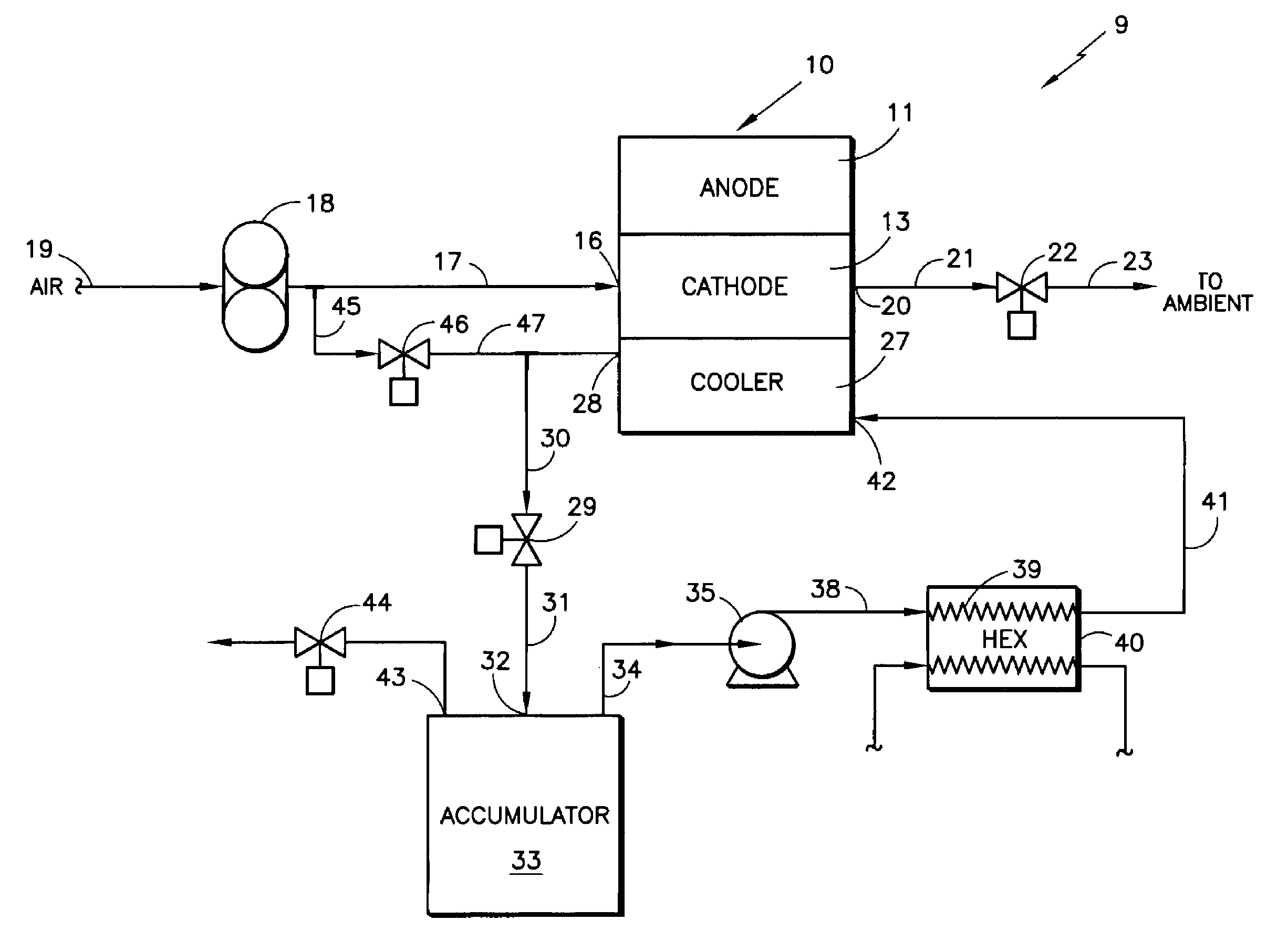
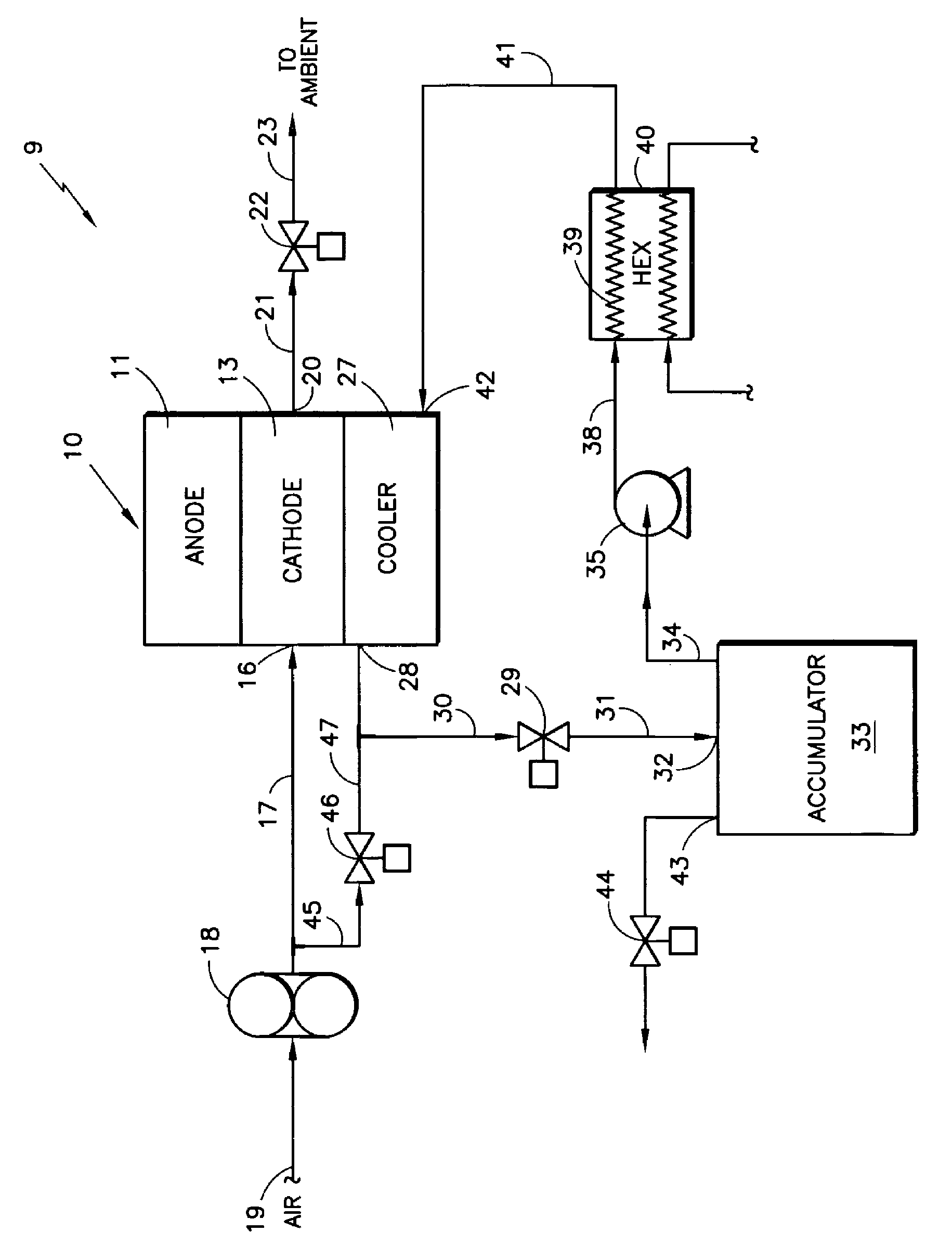
[0011]Referring to the FIGURE, a fuel cell power plant 9 employing the invention includes a fuel cell stack 10 which may be a conventional polymer electrolyte proton exchange membrane (PEM) fuel cell stack, including conventional anode flow fields 11, the configuration and nature of which are not peculiar to the present invention and need not be described further.

[0012]The stack 10 includes cathode flow fields 13 which provide oxidant gas to the cathode catalyst. The cathode flow fields are provided air at an inlet 16 through a conduit 17 from an air pump 18, receiving air through a conduit 19 from ambient. The exit 20 of the cathode flow fields is exhausted through a conduit 21 and a valve 22 to ambient 23.

[0013]The stack 10 has coolant flow fields 27, the exit 28 of which is connected through a valve 29 and conduits 30, 31 to the inlet 32 of a conventional accumulator 33. From the accumulator, coolant flows through a conduit 34, a coolant pump 35, over a conduit 38 and through the...


PUM

PropertyMeasurementUnit
temperatureaaaaaaaaaa
electrical poweraaaaaaaaaa
temperaturesaaaaaaaaaa

Abstract

The air blower (18) of a fuel cell power plant (9) is used to force water out of the coolant flow fields (27) of a fuel cell stack (10), a coolant pump (35) and a heat exchanger (40) through a valve (46) which is closed during normal operation. The water removal occurs as part of a shutdown procedure in which the fuel cell stack continues to operate so that it provides the power for the air pump and to assist in water removal (such as retaining low vapor pressure). The water flow to an accumulator (33) is blocked by a valve (29) during the shutdown procedure.

Description

[0001]This invention was made with the Government support under Agreement No. DTRS56-99-T-0015 awarded by the U.S. Department of Transportation, RSPA. The Goverment may have certain rights to this invention.TECHNICAL FIELD[0002]This invention relates to using the reactant air pump of a fuel cell power plant to force water out of coolant fields, coolant passageways and coolant equipment, as part of a shutdown procedure, utilizing power generated by the fuel cell power plant while it is still operational, just prior to shutdown.BACKGROUND ART[0003]Damage can occur to fuel cell power plant components as a result of water freezing, whenever a fuel cell power plant is to be non-operational in an ambient environment in subfreezing temperatures. It is known to have an accumulator placed at the lowest point in the coolant system so that freezable coolant that actually flows through the fuel cell stack can drain toward the accumulator. It is also known to use external pumps to blow air or in...

Claims


Application Information

Patent Timeline
Patent Type & Authority Patents(United States)
IPC IPC(8): H01M8/04
CPCH01M8/04029H01M8/04089H01M8/04179H01M8/04253H01M8/04223H01M8/04074Y02T90/32H01M2008/1095H01M2250/20Y02E60/50Y02T90/40H01M8/241H01M8/04228H01M8/0267H01M8/04H01M8/04303
Inventor WILSON, MATTHEW P.COUCH, HAROLD T.RESNICK, GENNADY
Owner AUDI AG
Why Eureka
Eureka Blog
Learn More