Accelerated compression ignition engine for HCCI

a compression ignition and hcci technology, applied in combustion engines, valve arrangements, machines/engines, etc., can solve the problems of low spark energy, low compression temperature, slow combustion of air-fuel mixtures in the otto cycle, etc., to reduce nox formation, high cranking torque, and high torque

Inactive Publication Date: 2011-09-15
WEST VIRGINIA UNIVERSITY
View PDF7 Cites 2 Cited by
  • Summary
  • Abstract
  • Description
  • Claims
  • Application Information

AI Technical Summary

Benefits of technology

[0007]The advantage of using compression ignition energy near TDC is the ability to ignite very lean air-fuel mixtures. This reduces NOx formation and eliminates the need for an air intake throttle valve. However, near idle speed, a throttle valve may still be needed to slow the engine speed. The advantage of using a fuel injector, in one embodiment, is that it enables enriching only that small amount of charge, involved in compression ignition, while not affecting the combustible mixture which is temporarily sealed inside the cylinder wall cavities, thereby providing charge stratification with a conventional steady flow injector. The cylinder wall cavities make a non-sinusoidal relationship possible between compression ratio and crank-angle, with second stage (or greater number of stages) compression / ignition possible. The sinusoidal relationship between compression ratio and crank angle in a conventional diesel engine with CR =20 to 30, peaks at 19° BTDC, with a required torque 187% to 270% higher than for a spark ignition engine at CR=10. Such high cranking torque makes it difficult to warm-up a diesel engine by cranking, unless a valve lifter is used. The high torque associated with cranking / starting a Diesel engine requires the engine to be much stronger and heavier than a spark ignition engine or the cylinder wall cavity engine claimed herein. Cranking torque required during near sinusoidal compression of a CR=10 spark ignition engine is similar to that of the herein claimed second stage compression ignition engine operating at CR 20. Thus, structure and weight will be about the same as a conventional spark ignition engine. Without need for a Diesel type fuel injector, this cycle can be scaled down to a fraction of a cubic inch displacement, for use in UAV's, chain saws, lawnmowers, string trimmers, etc.
[0008]Current small two-cycle engines have both inlet and exhaust ports located near the bottom of the piston stroke, and therefore, often use a domed piston to improve scavenging. However, when using cylinder wall cavities as in this invention, an exhaust valve can be added inside the cylinder wall cavity in one embodiment, as shown in FIG. 2, to provide unidirectional scavenging while using a flat piston. In four-cycle applications, the narrow piston to head clearance may delay intake valve opening.
[0009]The herein claimed engine configuration with cylinder wall cavities requires fewer parts than a spark ignition engine, has no need for spark plugs in at least one embodiment, can be operated on various fuels with lean mixtures to minimize NOx, and if used with Diesel fuel, may require some pre-heating of the combustible mixture, It extends engine life and miles per gallon due to the high lubricity and the heating value of diesel fuel.

Problems solved by technology

Slowly burning air-fuel mixtures in the Otto cycle is caused by low compression temperature, low spark energy, even when a near stoichiometric mixture is used.
Slow fuel burning in a Diesel cycle is due to time required for fuel injection, droplet vaporization and mixing with air.
But their mechanical complexity, high cost and limited engine speed prevents widespread usage.
However, near idle speed, a throttle valve may still be needed to slow the engine speed.
Such high cranking torque makes it difficult to warm-up a diesel engine by cranking, unless a valve lifter is used.
In four-cycle applications, the narrow piston to head clearance may delay intake valve opening.

Method used


Image

  • Accelerated compression ignition engine for HCCI
  • Accelerated compression ignition engine for HCCI
  • Accelerated compression ignition engine for HCCI

Examples


Embodiment Construction

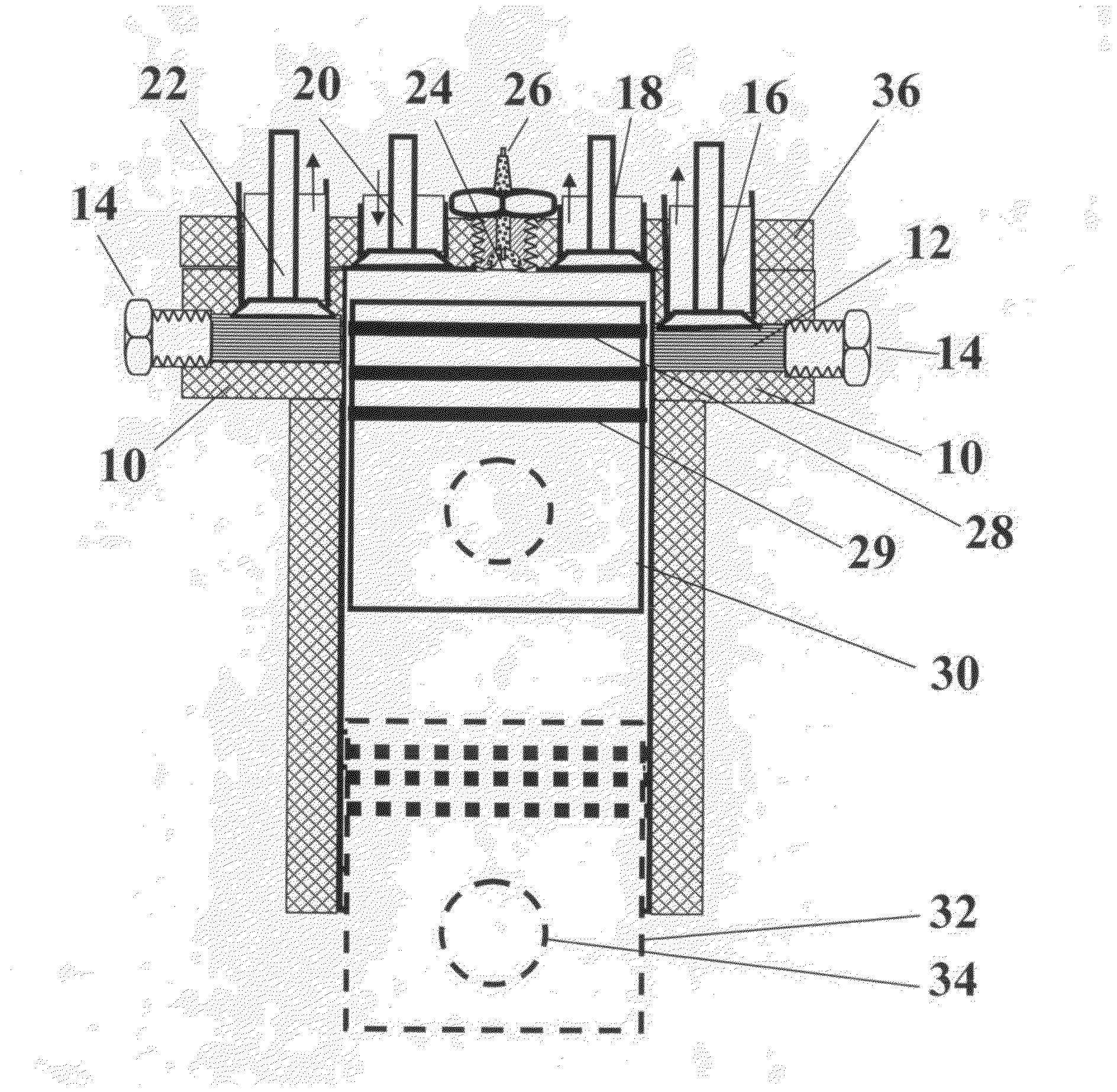
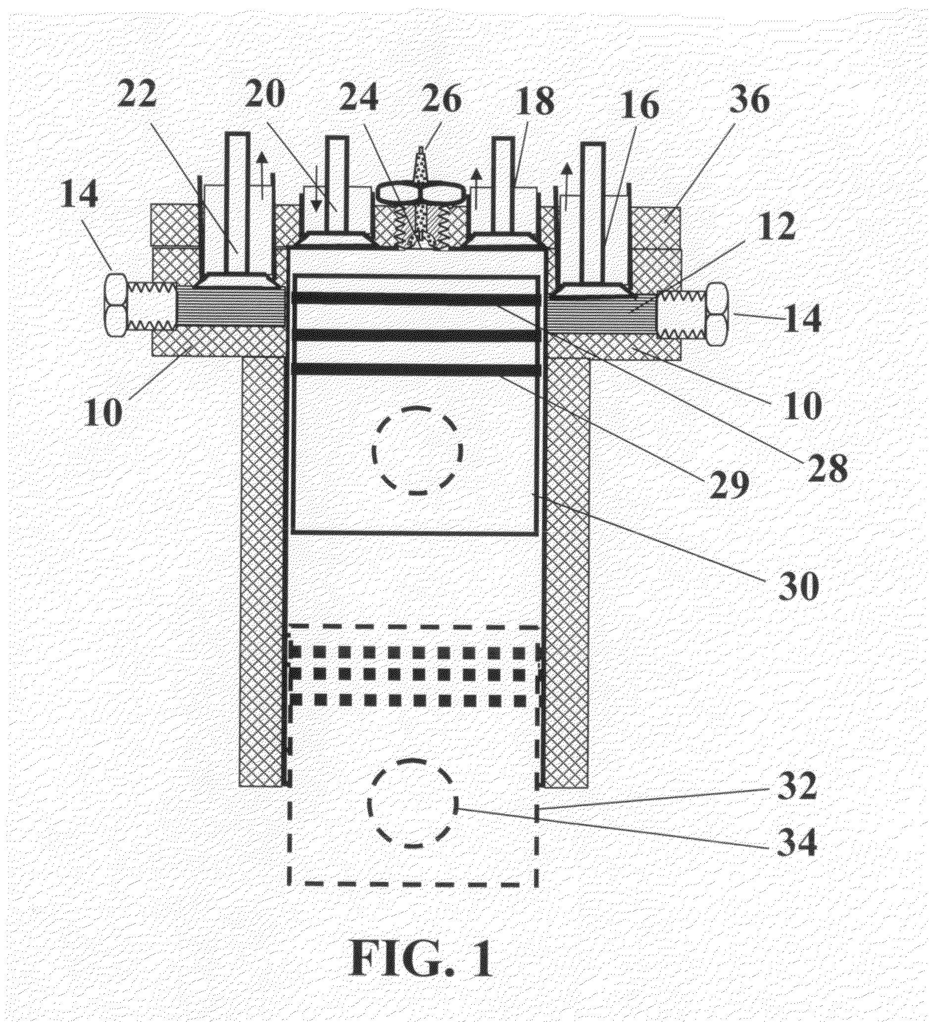
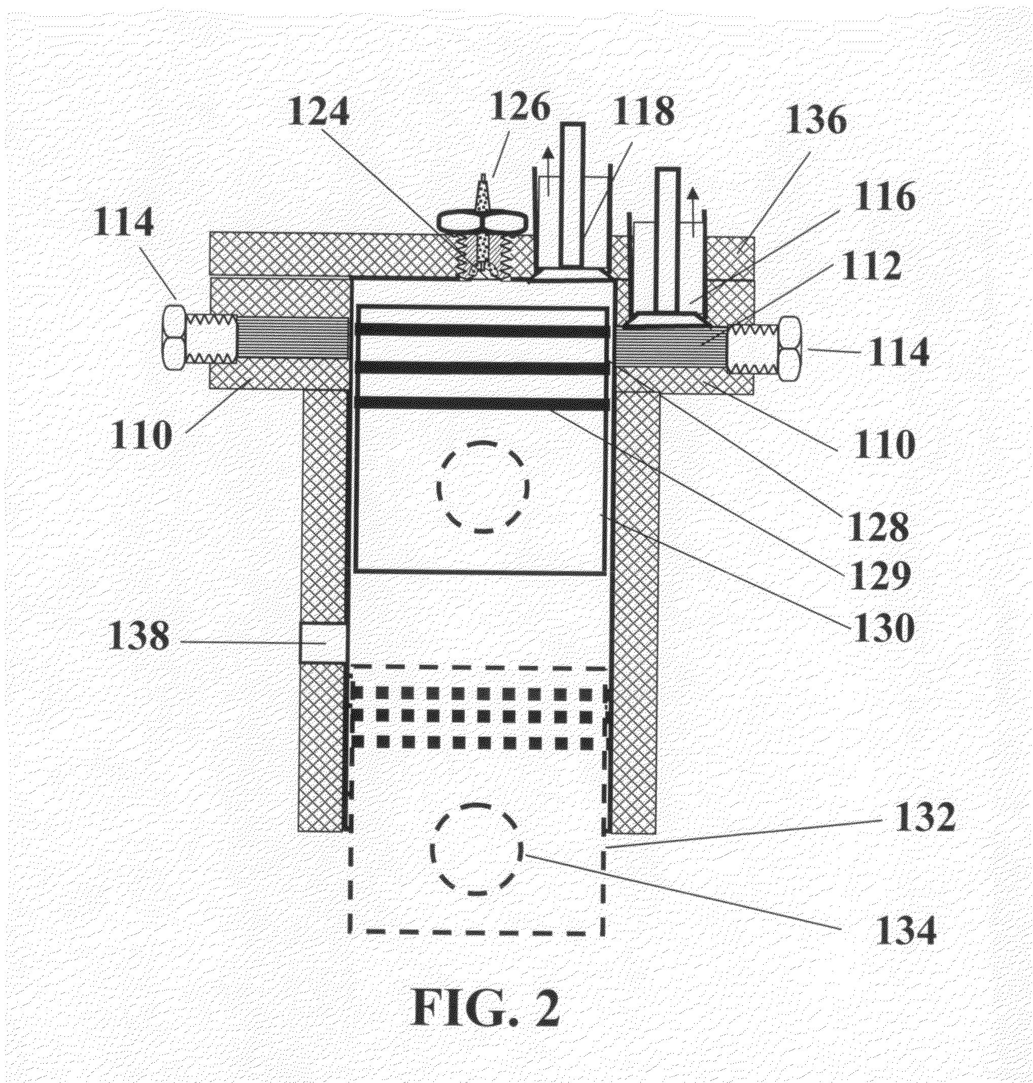
[0016]The configurations in the description and drawings in no way are meant to limit the physical configuration of the possible embodiments of internal combustion engines that may operate as described herein.

[0017]A spreadsheet calculation was used to quantify and graph typical compression performance parameters of a 500 cc displacement engine, operating on four different ideal cycles listed below.

1) Otto spark ignition at compression ratio CR=10,

2) Diesel compression ignition at CR=20

3) ACIE-20 / 12 is an abbreviation for: Accelerated Compression Ignition Engine in a spreadsheet with CR=20 at TDC and cylinder wall cavities closing at 12° before TDC.

4) ACIE-20 / 18 an abbreviation for: Engine with Cylinder-Wall-Cavities (CWC) in a spreadsheet with CR=20 at TDC and cylinder wall cavities closing at 18° before TDC.

[0018]A spreadsheet calculation was used to calculate and graph the ideal performance during the compression stroke of four cycles shown in FIG. 3 though FIG. 6. It assumed ope...


PUM


Abstract

An internal combustion engine has cylinder wall cavities located near the top dead center stroke end to allow optimizing the compression ratio in first stage compression, as function of fuel octane number used. The volume of the cylinder wall cavities is designed to be adjustable, even when the engine is operating. Using a conventional piston motion, the second stage compression becomes accelerated as soon the upper piston ring seals-off the cylinder wall cavities. This is due to the sudden significant reduction in volume. During the power stroke, after the upper piston ring opens the cylinder wall cavities; their fuel content is ignited by second stage combustion products. Because the torque required during accelerated compression is no greater than during first stage compression, stresses in the crankshaft are no more than in conventional spark ignition engines. This allows small displacement engines to be of light weight and to be hand cranked.

Description

CROSS-REFEREENCE TO RELATED APPLICATIONS[0001]This patent application claims priority to provisional patent application 61 / 339,999 filed on Mar. 11, 2010 which is incorporated by reference herein.FIELD OF THE INVENTION[0002]The engine disclosed herein operates using accelerated compression ignition in the range from volumetric compression ratio of 20 and above, without knock or associated high NOx production. This engine is applicable to a wide range of fuels.BACKGROUND OF THE INVENTION[0003]This patent application claims priority to provisional patent application 61 / 339,999 filed on Mar. 11, 2010 which is incorporated by reference herein.[0004]There are many different engine cycles based on a piston / cylinder configuration. Each such engine is designed for a specific application. They differ widely in mode of operation, maximum size, engine speed, power output per unit mass, most suitable fuel and method of ignition. Engine fuel efficiency increases with: 1) compression ratio (CR) u...

Claims


Application Information

Patent Timeline
Patent Type & Authority Applications(United States)
IPC IPC(8): F02B75/00
CPCF01L1/40F01L1/46F01L2003/25F01L2800/06Y02T10/128F02B25/04F02B41/04F02B2075/025F02D15/04F02B1/12Y02T10/12
Inventor LOTH, JOHN LODEWYK
Owner WEST VIRGINIA UNIVERSITY
Why Eureka
Try Eureka