Object sensor and controller

a technology applied in the field of object sensor and controller, can solve the problems of difficult to obtain sufficient response, inability to detect the hand of the user, and inability to provide etc., and achieve the effect of high response, high reliability and sufficient convenience of the system

Inactive Publication Date: 2007-10-16
OMRON AUTOMOTIVE ELECTRONICS CO LTD
View PDF25 Cites 46 Cited by
  • Summary
  • Abstract
  • Description
  • Claims
  • Application Information

AI Technical Summary

Benefits of technology

[0015]In addition, the “judging circuit part” comprises a filter for only outputting the signal component in the frequency range, among the signals received by the reflected wave receiving means, and a comparator for comparing the amplitude level of the output of the filter with a threshold value corresponding to a boundary of the predetermined range and turning on the detection output when the amplitude level is in the predetermined rage, for example. As a result, it can be simplified and miniaturized.
[0030]Therefore, the convenience of the system can be sufficiently provided and the problem such that the system is needlessly operated (the request signal is needlessly transmitted and the battery of the vehicle is wasted or the standby power in the building is needlessly increased) by the error detection (erroneous generation of the trigger) can be considerably prevented. In additions since it is not necessary to change the configuration or the size of the handle of the opening and closing part, the degree of freedom in its design is not strictly limited. In addition, as described above, since the power consumption of the object sensor for generating the trigger is extremely low as compared with the constitution in which the conventional impulse radar is mounted for generating the trigger as it is, the power consumption in the building can be considerably lowered and the problem such that the battery of the vehicle runs out can be solved.

Problems solved by technology

However, the above-described detection device has the following problems.(a) In the case of the optical sensor, malfunction could occur because of a stain or a foreign object (rain or a dead leaf, for example).(b) Since a detection area is small (a detection distance is short), it is difficult to obtain sufficient response so that a problem could occur in the operation of the applied system.
Especially, in the case of the electrostatic capacity type of sensor or the mechanical type of switch, the hand of the user is not detected until the hand completely touches the sensor.
Thus, in the constitution in which at least the sensor is simply attached to the door handle, since the communication with the portable machine is established after the user starts to pull the door handle to open the door and then the automatic unlocking operation is performed the above problem surely occurs.(c) Since it is necessary to provide a sensor element which is relatively large and hard to be incorporated, at a place (the door handle of the vehicle, for example) in which the approaching object is to be detected, it is necessary to considerably change a configuration or a size of the place in which the approaching object is to be detected.
As a result, the degree of freedom in design at the place is largely limited.
Especially, when the hand of the user approaching the door handle of the vehicle is to be detected by the optical sensor or the mechanical type of switch with high response as much as possible, it is necessary to arrange a light-emitting element or a light-receiving element in the vicinity of the door handle or to arrange a contact of the mechanical type of switch at a place projecting from the. door handle, which considerably affects a deign of the door handle or the car body in the vicinity of it.< / ul
However, since the conventional impulse radar performs complicated judging processes (many waveforms of the reflection waves are sampled, compared and analyzed to determine the existence of the specific object) using a microcomputer, its power consumption is high.
Consequently, it was found that it could not be applied to the object sensor of the vehicle using a battery as a power supply.
Consequently, the power consumption for the detecting operation has to be lowered as much as possible, otherwise the battery of the vehicle runs out soon, that is, the power has to be saved several orders of magnitude more than the landmine detector.
As a result, the conventional impulse radar cannot be applied as it is.

Method used


Image

  • Object sensor and controller
  • Object sensor and controller
  • Object sensor and controller

Examples


first embodiment

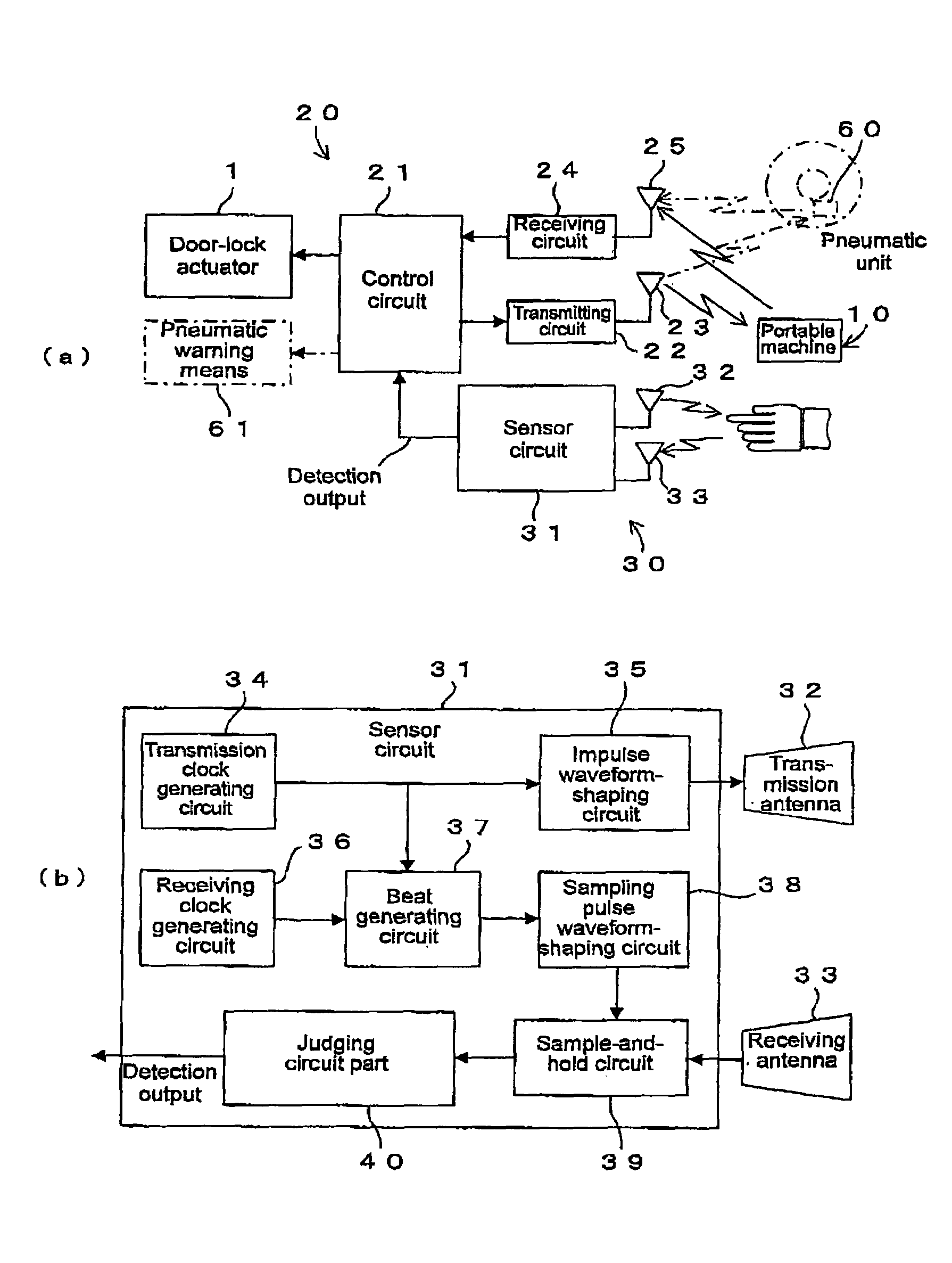
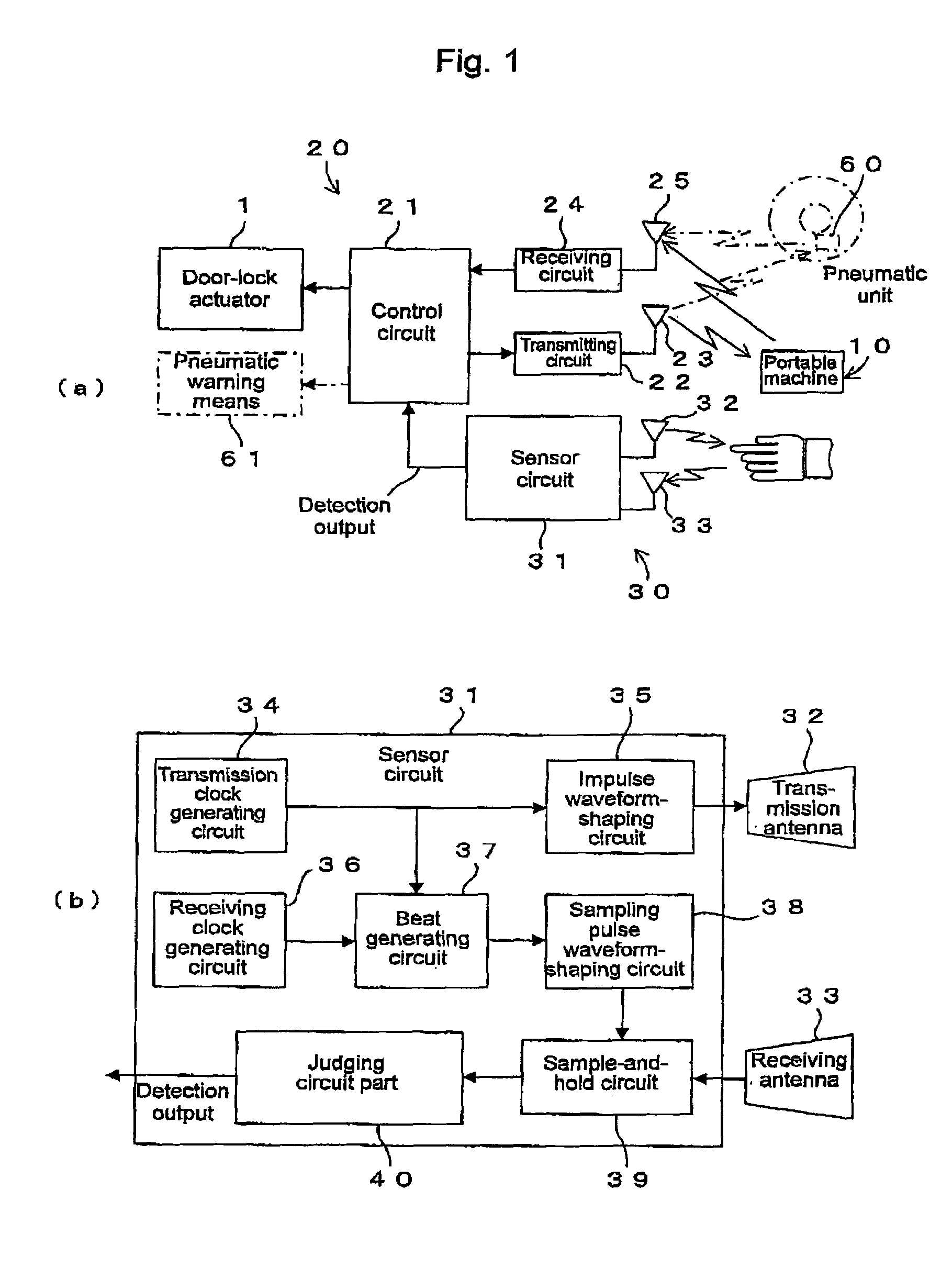
[0045]A first embodiment of the present invention is described. According to this embodiment, the present invention is applied to a controller of a passive entry system of a vehicle (or a tire pneumatic malfunction warning system). As shown in FIG. 1(a), this system comprises a portable machine 10, a body machine 20 and an object sensor 30 which are mounted on the vehicle.

[0046]The portable machine 10 comprises an antenna or a receiving circuit for receiving a seizing signal in a low frequency (LF) such as 100 to 150 kHz, a transmitting circuit or an antenna for wirelessly transmitting an answer signal or a manipulation signal (a locking manipulation signal or an unlocking manipulation signal) in a high frequency (a frequency in UHF band, for example) as will be described below, storing means (EEPROM, for example) on the portable machine side for storing at least a certification code (referred to as ID code also), a control circuit comprising a microcomputer for controlling the whol...

second embodiment

[0103]Next, a second embodiment is described with reference to FIGS. 10 and 11. According to this embodiment, the present invention is applied to a controller in a passive entry system of a building (residence or an office, for example) FIGS. 10(a) and 11(a) are front views of a door of the building, FIGS. 10(b) and 11(b) are sectional views of the door and FIG. 11(c) is an enlarged front view of the door. The same components as in the first embodiment are allotted to the same reference numerals and descriptions of them are omitted.

[0104]The circuit constitution and its processing contents may be the same as in the first embodiment shown in FIGS. 1 to 4. Arrangement of each component may be as follows, for example.

[0105]In a case of a bar-shaped door handle as shown in FIG. 10(a), a transmission antenna 32 and a receiving antenna 33 of an object sensor 30 are formed to a simple bar shape so as to correspond to the door handle and each component is arranged as shown in FIG. 10(b). Th...


PUM


Abstract

A sensor for detecting a specific object (such as a hand) excellent in operation reliability and response, further excellent in mountability (dominance such as in size and design) on a vehicle, and much less in power consumption than conventional impulse radars. The object sensor comprises detecting wave transmitting means and reflected wave receiving means of an impulse radar and a judging circuit part (40) for turning on the detection output when the amplitude level of a signal component, in a frequency range corresponding to the moving speed range of a specific object, of a signal received by the reflected wave receiving means lies in a predetermined range corresponding to the reflection characteristics of the specific object.

Description

TECHNICAL FIELD[0001]The present invention relates to an object sensor which is suitable for being used when a hand of a user of a vehicle approaching a door handle is detected in order to trigger an automatic unlocking operation of a passive entry system of the vehicle, for example, and a controller using the above sensor.BACKGROUND ART[0002]Recently, according to an entry system of a vehicle, there has been proposed a device provided in a vehicle which performs an automatic operation by establishing bidirectional communication between a portable machine carried by a vehicle user and a body machine mounted on the vehicle, and then confirming necessary cross-check, which is partially put to practical use.[0003]According to the bidirectional communications since an answer signal including a necessary code is automatically transmitted from the portable machine to the body machine in response to a request signal (a seizing signal activating the portable machine, for example) transmitte...

Claims


Application Information

Patent Timeline
Patent Type & Authority Patents(United States)
IPC IPC(8): B60R25/00G05B19/00G08B29/00G06F7/00H04B1/00E05B81/78E05B83/36E05B85/16G01S13/56G01S13/75G07C9/00
CPCB60R25/246E05B81/78G07C9/00309G07C9/00007E05B81/77G01S13/56G07C2209/65G07C2009/00396G07C2209/64G07C9/20
Inventor NAKAMURA, AKIHIKONISHIDAI, TETSUOSATO, YASUHIRONISHIGUCHI, TADAOISHIHARA, NAOYUKI
Owner OMRON AUTOMOTIVE ELECTRONICS CO LTD
Why Eureka
Try Eureka