Face lighting for edge location in catalytic converter inspection

a technology for catalytic converters and edge locations, applied in the direction of instruments, measurement devices, scientific instruments, etc., can solve the problems of affecting performance and sealing, affecting the performance of the catalytic converter, and being easily damaged by the catalytic converter

Inactive Publication Date: 2007-10-16
SMITHGALL & ASSOCS +1
View PDF7 Cites 40 Cited by
  • Summary
  • Abstract
  • Description
  • Claims
  • Application Information

AI Technical Summary

Benefits of technology

[0007]It is a further object, feature, or advantage of the present invention to provide for using imaging technologies to inspect objects such as catalytic converters for edge chips.
[0008]It is a still further object, feature, or advantage of the present invention to provide a method and system for inspecting catalytic converters that is practical and not cumbersome.
[0009]Another object, feature or advantage of the present invention is to evaluate an object for edge chips using only a single camera.
[0010]Yet another object, feature, or advantage of the present invention is to evaluate an object for edge chips as the object is moving during a manufacturing or production process.
[0011]A further object, feature, or advantage of the present invention is to provide a method for inspecting an object for edge chips that can be used to inspect 100 percent of all product produced or processed in a plant.
[0012]One or more of these and / or objects, features, or advantages of the present invention become apparent from the specification and claims that follow. The present invention is not to be limited by these objects or the Background of the Invention.

Problems solved by technology

Catalytic converters are typically fragile ceramic blocks which can easily be damaged.
Due to the fragility of these ceramic blocks, the catalytic converters can be easily damaged particularly on the edges.
These edge chips affect the performance and sealing of the catalytic converters into an enclosure.
Thus, the presence of edge chips is a significant problem in catalytic converter manufacturing.
One of the problems with some inspection processes is their complexity.
The complexity can include using multiple cameras, rotating objects or other cumbersome techniques.
Using multiple cameras to view edges from different angles by rotating the object would be more cumbersome and more complex.

Method used


Image

  • Face lighting for edge location in catalytic converter inspection
  • Face lighting for edge location in catalytic converter inspection
  • Face lighting for edge location in catalytic converter inspection

Examples


Embodiment Construction

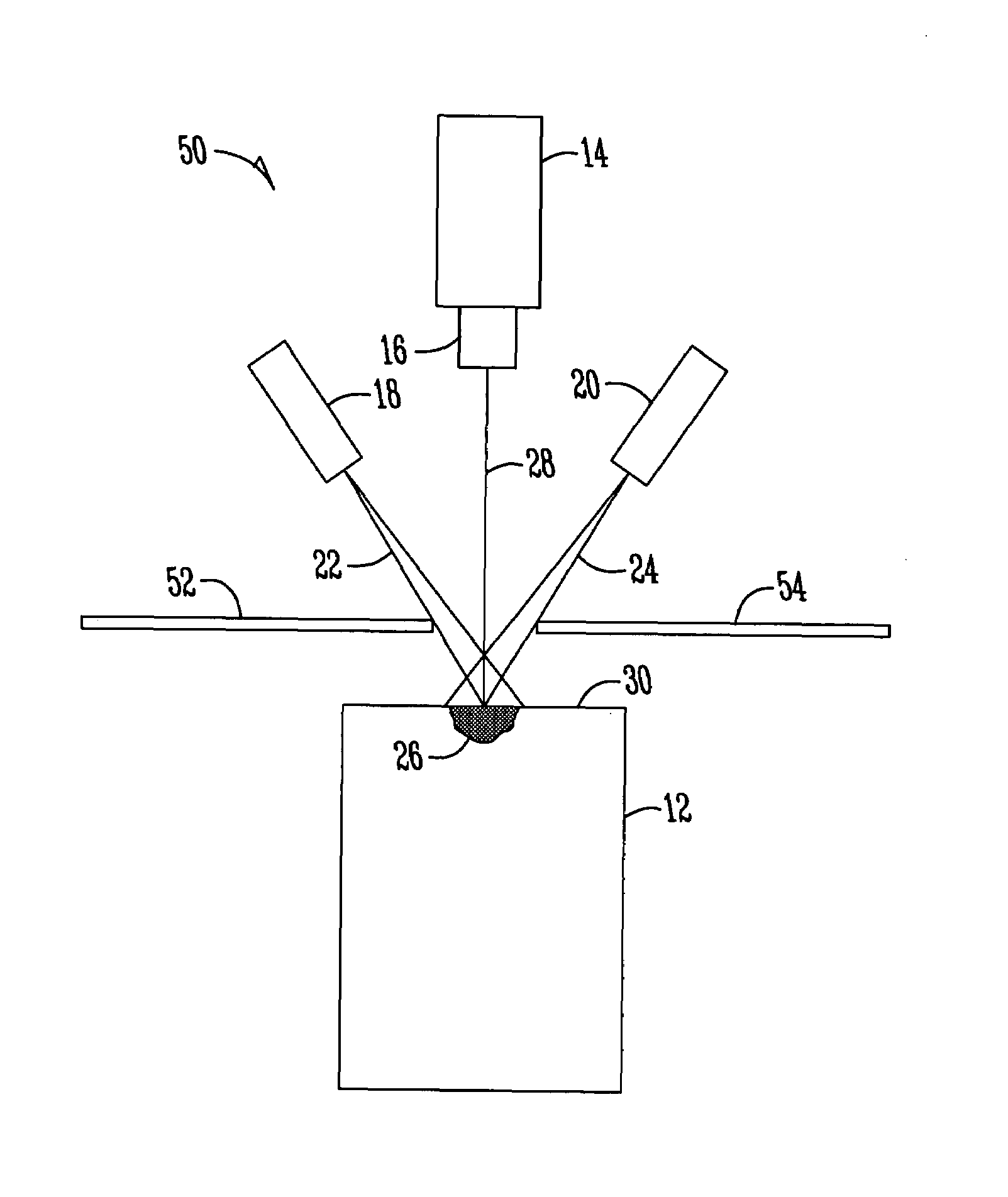
[0020]The present invention provides for a method and system for inspecting objects such as catalytic converts or other objects having a substantially planar face with surface variations that make detection of edge chips difficult using conventional approaches.

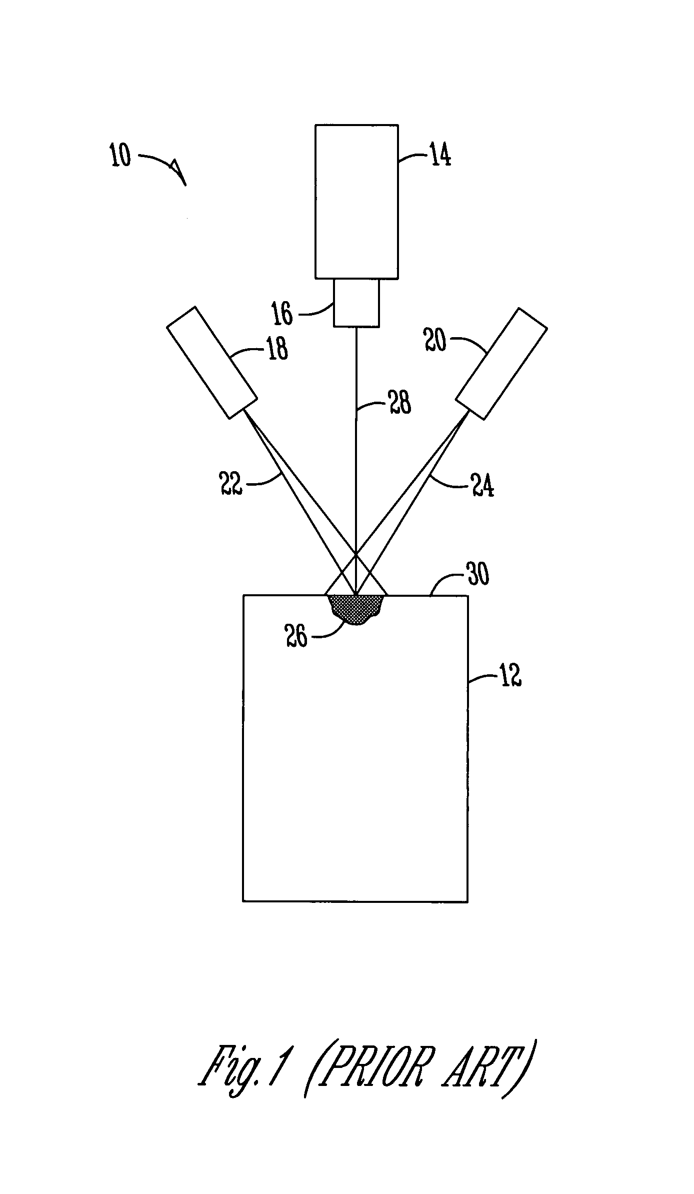
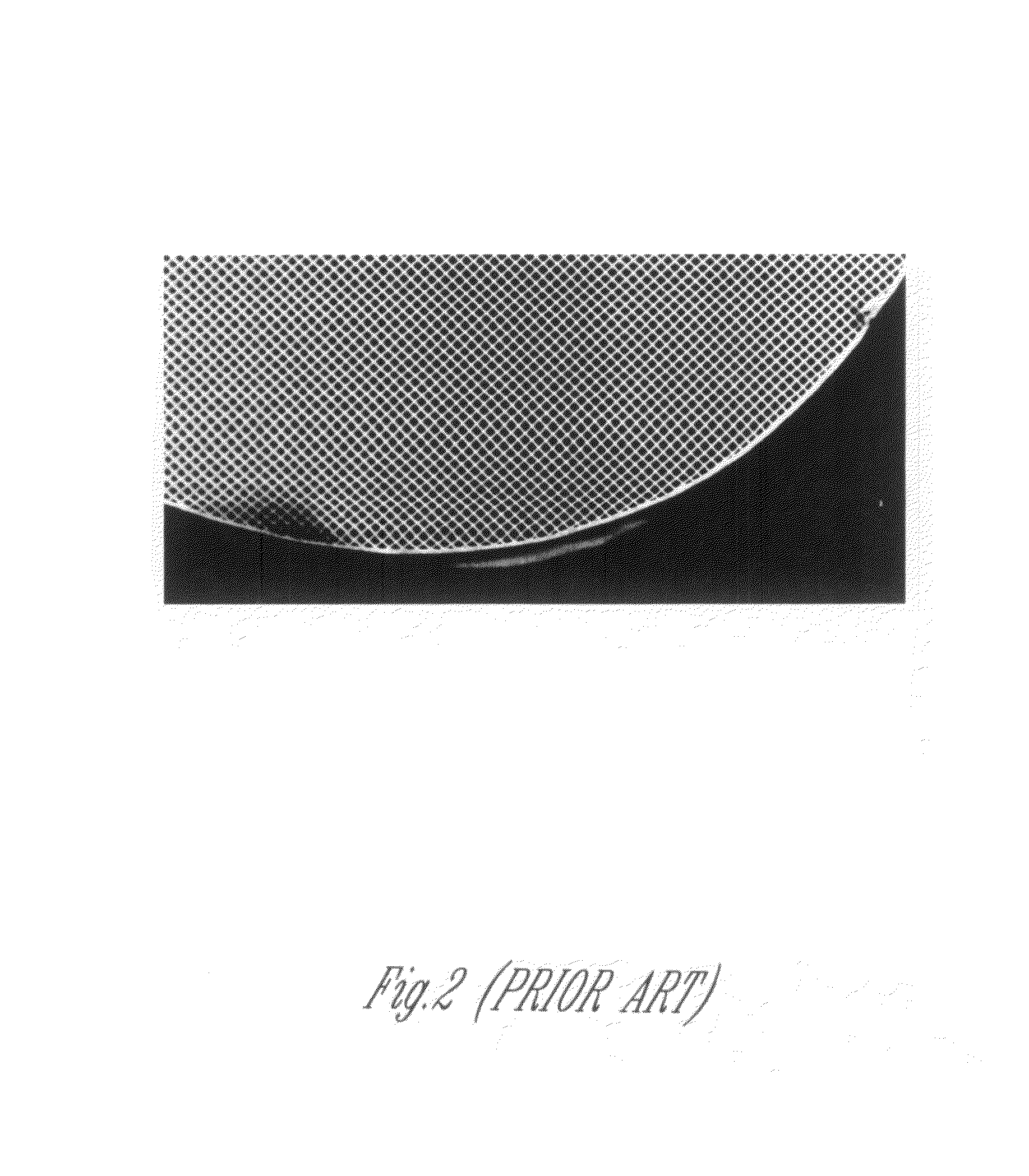
[0021]FIG. 1 illustrates a prior art system for inspecting an object such as a catalytic converter. In such a system, the object 12 is moving through a production process, such as on a conveyor belt or other mechanism. A camera 14 with a lens 16 looks downwardly on the face 30 of the object 12 as the object moves across the view of the camera 14. A line 28 indicates the optical axis between the camera 14 and the object 12. Light sources 18 and 20 are positioned on opposite sides of the camera 14. Both the light sources 18 and 20 are positioned at an angle relative to the optical axis 28. Light 22 and 24 is emitted from the light sources 18 and 20 to illuminate the planar surface 30 of the object 12. An edge chip or gouge 26 is...


PUM

PropertyMeasurementUnit
lighting angleaaaaaaaaaa
depth fieldaaaaaaaaaa
depth field of lightingaaaaaaaaaa

Abstract

A method and system for inspecting an object having a planar face with surface variations such as catalytic converters. Light sources are placed above the planar face of the object for lighting the face of the object. At least one obscuration is positioned proximate the planar face of the object to limit the lighting of the planar face of the object to thereby provide a low depth field of lighting. The planar face of the object is imaged to provide an image representation of the planar face of the object. The image representation of the planar face of the object is evaluated to characterize edge chip damage.

Description

BACKGROUND OF THE INVENTION[0001]The present invention relates to imaging technologies for inspection of devices such as, but not limited to, catalytic converters. More specifically, but not exclusively, the present invention relates to evaluating the presence or absence or edge chip damage for an object such as a catalytic converter. The problems in the art addressed by the present invention are described in terms of catalytic converters. The present invention, however, is not limited to catalytic converters, but can be used in other applications as well.[0002]Catalytic converters are typically fragile ceramic blocks which can easily be damaged. Catalytic converters are comprised of a plurality of parallel tubes to form a honeycomb structured object. Due to the fragility of these ceramic blocks, the catalytic converters can be easily damaged particularly on the edges. This damage may be referred to as edge chips. These edge chips affect the performance and sealing of the catalytic ...

Claims


Application Information

Patent Timeline
Patent Type & Authority Patents(United States)
IPC IPC(8): G01N21/00
CPCG01N21/95692G01N21/9515
Inventor SMITHGALL, BRIAN
Owner SMITHGALL & ASSOCS
Why Eureka
Try Eureka