
Method and apparatus reducing off track head motion due to disk vibration in a hard disk drive

a technology of hard disk drive and head gimbal, which is applied in the direction of maintaining head carrier alignment, recording information storage, instruments, etc., can solve the problems of substantial pes, non-uniform air bearing, and difficulty in adjusting the angle of the slider, so as to reduce the center of the slider and reduce the displacement of the off-track

Inactive Publication Date: 2007-10-16
SAMSUNG ELECTRONICS CO LTD
View PDF14 Cites 29 Cited by
  • Summary
  • Abstract
  • Description
  • Claims
  • Application Information

AI Technical Summary

Benefits of technology

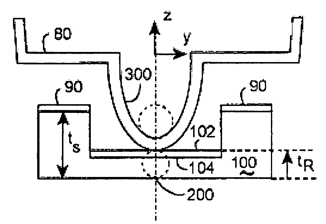
[0014]The invention includes sliders provided with indented back-side surfaces, which reduce the slider roll center to less than the slider's effective thickness. The back-side surface is opposite the front side of the slider with the read-write head, which faces the rotating disk surface in a hard disk drive. Head gimbal assemblies built with these sliders may reduce off-track displacements induced by disk vibration.
[0017]The slider contact covers may couple with the slider through an indented surface located closer than the slider thickness to the front-side of the slider. Such embodiments may have a negative slider roll center, which preferably minimizes the total TMR displacement of the head gimbal assembly in the presence of disk vibration. In certain further preferred embodiments, the negative slider roll center may effectively eliminate the total TMR displacement in the presence of disk vibration.

Problems solved by technology

A substantial portion of the PES is caused by disk vibration.
This approach has some problems.
The air bearing becomes non-uniform when the disk surface is flat, adding new mechanical instabilities into the system.
This scheme does not cause a non-uniform air bearing when the disk surface is flat.
However, the way the effective roll axis is placed inside the disk requires a more complex mechanical coupling between the slider support assembly and the slider.
This complex mechanical coupling has a greater probability of mechanical failure, tending to increase manufacturing expenses and to reduce hard disk drive life expectancy.

Method used


Image

  • Method and apparatus reducing off track head motion due to disk vibration in a hard disk drive
  • Method and apparatus reducing off track head motion due to disk vibration in a hard disk drive
  • Method and apparatus reducing off track head motion due to disk vibration in a hard disk drive

Examples


Embodiment Construction

[0052]The following description is provided to enable any person skilled in the art to make and use the invention and sets forth the best modes presently contemplated by the inventors of carrying out the invention. Various modifications, however, will remain readily apparent to those skilled in the art, since the generic principles of the present invention have been defined herein.

[0053]Disclosed are improved head gimbal assemblies addressing TMR. They support parallel flying sliders over flat disk surfaces, and reduce TMR induced by disk vibration.

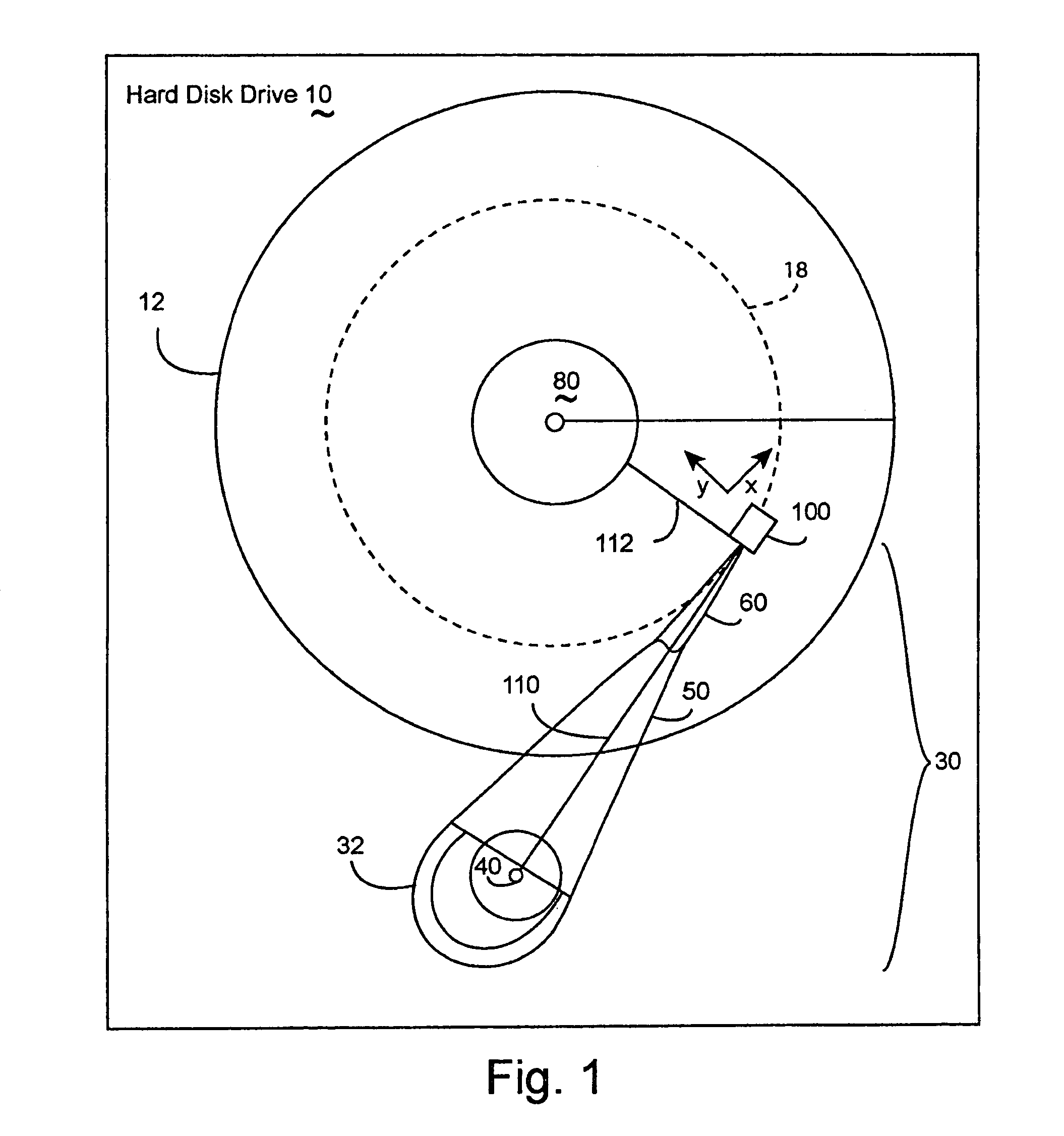
[0054]Referring to the drawings, more particularly by reference numbers, FIG. 1 shows an example actuator arm assembly 30 pivoting about the actuator axis 40, changing the angle between the radial vector 112 and the actuator principal axis 110. The actuator arm assembly 30 includes the actuator arm 50 coupled to head gimbal assembly 60, which is coupled to slider 100.

[0055]In FIG. 1, the X axis extends along the principal axis 110 of the ...


PUM

PropertyMeasurementUnit
heightaaaaaaaaaa
thicknessaaaaaaaaaa
magnetic fieldsaaaaaaaaaa

Abstract

The invention includes sliders provided with indented surfaces, reducing the roll center for head gimbal assemblies below the effective thickness of the slider. Head gimbal assemblies built with these sliders may reduce off-track displacements induced by disk vibration. The load beam gimbal may contact the indented surface, creating a slider roll center less than the slider thickness. Alternatively, the sliders may include a slider contact cover interfacing to the load beam forming the gimbal. The slider contact covers may couple with the slider through an indented surface located closer than the slider thickness. These may have a negative slider roll center. The invention includes actuator arms, actuator assemblies, and hard disk drives including these head gimbal assemblies. The invention includes making the invention's sliders, head gimbal assemblies, actuator arms, actuator assemblies, and hard disk drives. The invention includes the products of these processes.

Description

BACKGROUND OF THE INVENTION[0001]1. Field of the Invention[0002]The present invention relates to the sliders and the head gimbal assemblies of a hard disk drive.[0003]2. Background Information[0004]Hard disk drives contain one or more magnetic heads that are coupled to rotating disks. The heads write and read information by magnetizing and sensing the magnetic fields of the disk surfaces. Magnetic heads have been developed that have a write element for magnetizing the disks and a separate read element for sensing the magnetic field of the disks. The read element is typically constructed from a magneto-resistive material with a resistance that varies with the magnetic fields of the disk. Heads with magneto-resistive read elements are commonly referred to as magneto-resistive (MR) heads.[0005]Each head is embedded in a slider, which is attached to a flexure arm to create a subassembly commonly referred to as a head gimbal assembly (HGA). The HGA's are attached to an actuator arm. The ...

Claims


Application Information

Patent Timeline
Patent Type & Authority Patents(United States)
IPC IPC(8): G11B5/48G11B5/60
CPCG11B5/4826
Inventor OH, DONG-HOKANG, SEONG-WOOLEE, HAENG-SOOMORRIS, FRANK IVANBOLJANOVIC, MOMO K.KIM, YOUNG-HOON
Owner SAMSUNG ELECTRONICS CO LTD
Learn More