
Optical fiber transmission system with increased effective modal bandwidth transmission

a technology of optical fiber and effective modal bandwidth, applied in the direction of optical waveguide light guide, multimode transmission, instruments, etc., can solve the problems of low bandwidth-distance products and unsuitable for many state-of-the-art communication systems

Inactive Publication Date: 2007-10-16
II VI DELAWARE INC
View PDF15 Cites 18 Cited by
  • Summary
  • Abstract
  • Description
  • Claims
  • Application Information

AI Technical Summary

Benefits of technology

The present invention relates to methods and apparatus for reducing modal noise and increasing the effective modal bandwidth of optical fiber transmission systems. The invention aims to address the problem of modal noise, which is the noise penalty at the receiver caused by time-varying modal losses in the detected optical signal. The invention proposes various methods and apparatus to reduce modal noise and increase the effective modal bandwidth, including the use of spatial mode optical converters, electro-absorption modulators, and laser modulators. The invention also includes dynamic reoptimization and electronic dispersion compensation for optical receivers. Overall, the invention aims to improve the performance and reliability of optical fiber transmission systems.

Problems solved by technology

Known multimode optical fiber transmission systems, however, have relatively low bandwidth-distance products for a given bit error rate (BER) and, therefore, are not suitable for many state-of-the art communication systems.

Method used


Image

  • Optical fiber transmission system with increased effective modal bandwidth transmission
  • Optical fiber transmission system with increased effective modal bandwidth transmission
  • Optical fiber transmission system with increased effective modal bandwidth transmission

Examples


Embodiment Construction

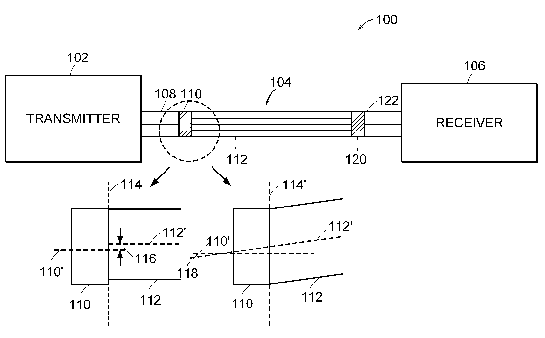
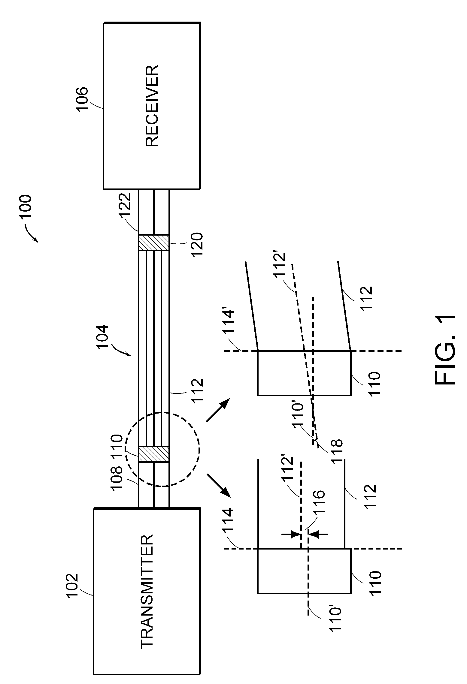
[0013]The present invention relates to methods and apparatus for reducing modal noise generation and increasing the effective modal bandwidth of optical fiber transmission systems. The term “modal noise” is described herein to mean the noise penalty at the receiver that is caused by time-varying modal losses in the detected optical signal.

[0014]Modal noise is generated when optical modes of the optical signal propagate through regions in an optical fiber that create mode selective losses (MSL). The term “mode selective loss (MSL)” is defined herein as a loss in a multimode fiber optic cable that results in a non-uniform loss to the modes traveling in the optical fiber. Mode selective losses can be caused by geometrical discontinuities in the optical path, such as geometrical discontinuities caused by physical bends in the optical fiber, fiber defects, and contamination proximate to the optical fiber connector. Mode selective losses can also occur in spatial mode converters or optica...


PUM


Abstract

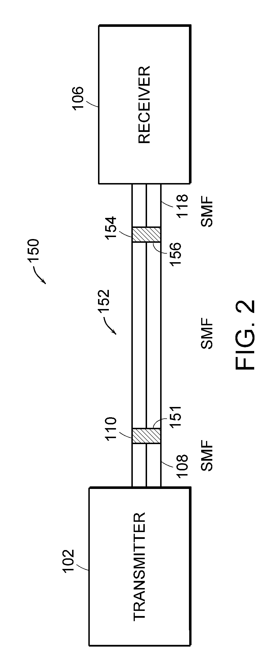
A multi-mode optical fiber link is described that includes a single-mode optical fiber having an input that receives an optical signal for transmission through the multi-mode optical fiber link. A first spatial mode converter is coupled to the single-mode optical fiber. The first spatial mode converter conditions a modal profile of the optical signal for propagation through a multi-mode optical fiber. A multi-mode optical fiber is coupled to an output of the first spatial mode converter. A second spatial mode converter is coupled to an output of the multi-mode optical fiber. The second spatial mode converter reduces a number of optical modes in the optical signal. Both the first and the second spatial mode converters increase an effective modal bandwidth of the optical signal propagating through an output of the second spatial mode converter.

Description

CROSS REFERENCE TO RELATED APPLICATIONS[0001]This patent application is a continuation-in-part of U.S. patent application Ser. No. 10 / 605,490, filed on Oct. 2, 2003 now abandoned, entitled “Optical Fiber Transmission system with Increased Effective Modal Bandwidth Transmission,” which is a continuation-in-part of U.S. patent application Ser. No. 10 / 605,107, filed on Sep. 9, 2003, entitled “Optical Transmitter for Increased Effective Modal Bandwidth Transmission,” which claims priority to U.S. provisional patent application No. 60 / 481,166, filed on Aug. 1, 2003, entitled “Optical Fiber Transmission System with Increased Effective Modal Bandwidth.” The entire disclosure of U.S. patent application Ser. No. 10 / 605,490, U.S. patent application Ser. No. 10 / 605,107 and U.S. provisional patent application number 60 / 481,166 are incorporated herein by reference.BACKGROUND OF INVENTION[0002]Many existing optical fiber transmission systems use multi-mode optical fiber. Multi-mode optical fiber ...

Claims


Application Information

Patent Timeline
Patent Type & Authority Patents(United States)
IPC IPC(8): G02B6/26G02B6/42G02B6/14H04B10/2581
CPCH04B10/2581G02B6/14
Inventor HALLEMEIER, PETERCOLYAR, MARKGERTEL, EITANEREIFEJ, HEIDER NAIM
Owner II VI DELAWARE INC
Learn More